
Sacroiliac screw
a technology of sacroiliac screw and screw body, which is applied in the field of spinal fixation screw, can solve the problems of hypermobility of the joint, difficult diagnosis of hypermobility, and difficult treatment of excessive pain, and achieve the effect of strengthening fusion
Patent Information
- Authority / Receiving Office
- US · United States
- Patent Type
- Patents(United States)
- Current Assignee / Owner
- Publication Date
- 2018-04-17
Smart Images
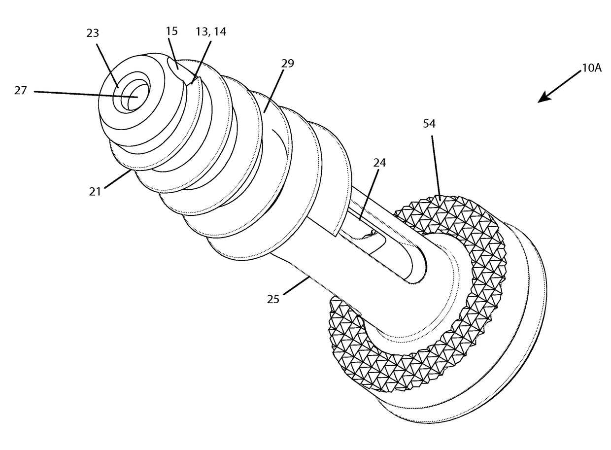
Figure 1 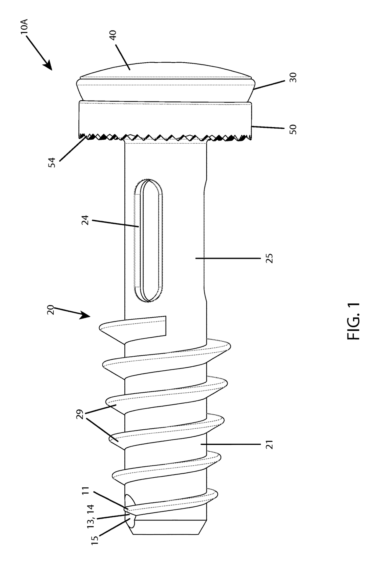
Figure 2 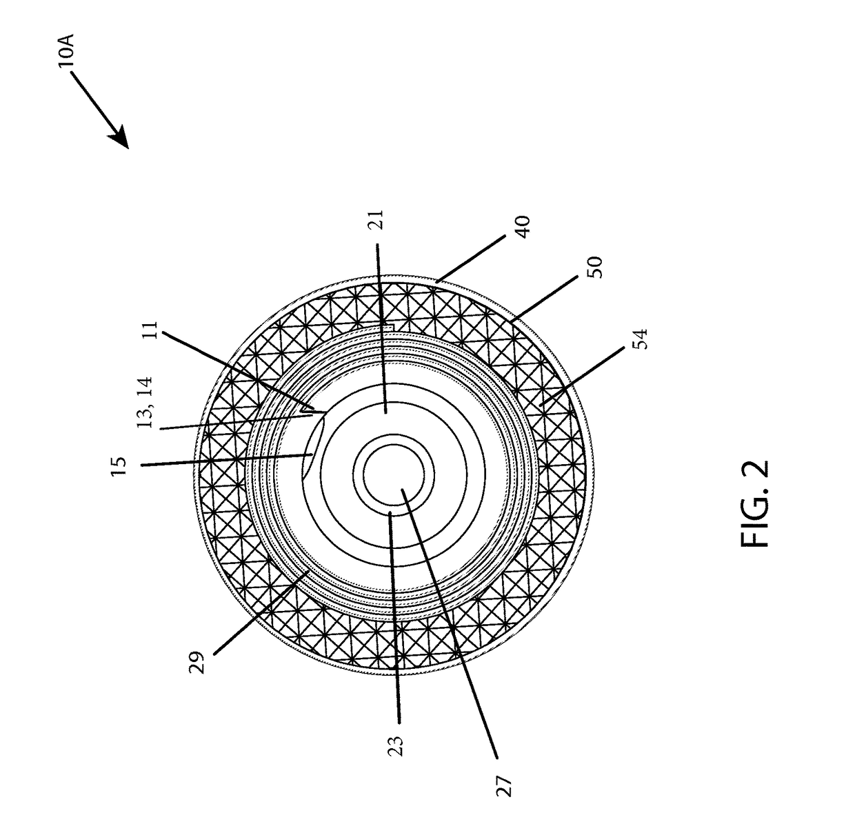
Figure 3
Abstract
Description
RELATED APPLICATIONS
[0001] This application is a continuation in part of U.S. application Ser. No. 14 / 630,748 entitled “Improved Sacroiliac Screw” filed Feb. 25, 2015.TECHNICAL FIELD
[0002] The present invention relates to an improved spinal fixation screw for transiliac fixation and a method of use.BACKGROUND OF THE INVENTION
[0003] Many complaints of lower back pain and leg pain have been attributed to herniated discs or other injuries to the spinal column. Extensive therapy and treatment has often been unsuccessful in alleviating such pain. It has been established that some of this lower back and leg pain can be attributed to symptomatic sacroiliac dysfunction or instability. Normally, the sacroiliac joint which spans between the sacrum bone and ilium bone has nutation of one to two degrees. “Nutation” is the medical term which describes the relative movement between the sacrum and ilium. A patient's sacroiliac joint can become damaged resulting in hypermobility of the joint. Because ...
Examples
first embodiment
[0038]In FIGS. 1-8B, the screw 10A has one cutting flute 11. As shown in FIGS. 1, 4A and 5, the cutting edge 13 lies in a plane almost or substantially parallel to the axis of the screw shaft and each had a ramp 14 for directing bone fragments to a bone receiving opening 15 positioned in front of a start of one thread above the tip end into the hollow chamber 12 and is preferably oriented perpendicular to the helical thread start. The cut fragments spiral along the ramped surfaces 14 where they bend and break into bone fragments as they enter the opening 15.
[0039]With reference to FIGS. 8A and 8B, an exploded view of the first embodiment shows a washer 50 with a concavity 52 in the form of a polyaxial shaped bowl to receive the bottom 32 of the head 30 which has a rounded or polyaxial hemispherical curvature. This feature allows the washer 50 to occupy a space between the screw head 30 and the bone on tightening and can accommodate any angulation so the washer 50 stays flush against...
second embodiment
[0040]In FIGS. 9-16B, there are two cutting flutes 11, one flute 11 at each start of the threads 28, 29 directly in front of and partially overhanging a bone receiving opening 15. Each flute 11 is diametrically opposed from the other and each has a cutting edge 13 formed from a start or leading end of a thread 28, 29 adjacent or near the tip end 21. The cutting edges 13 are still circumferentially in a plane about parallel to the axis, but are positioned diametrically opposite at each thread start and overhanging the opening 15 ahead of the flutes 11. Both flutes 11 capture the cut bone fragments and direct them into the chamber 12 in pieces that are broken on threading by having the ramp surfaces 14 pushing the bone fragments into the openings 15 during implantation.
third embodiment
[0041]With reference to FIGS. 2, 7A, 10 and 15B, a third embodiment, an annular ledge 23 extends across the hollow shaft 20 at the tip end 21. The ledge 23 has an aperture 27 for receiving a guide wire. This third version screw has the same flutes 11 as shown in FIG. 1 or 2.
[0042]FIGS. 7A-8B and FIGS. 15A-16B show a threaded driver cap 40 with tool aperture 41 inserted and threaded into the threads 33 of the enlarged head 30. This screw head 30 has a torque receiving cavity 41A with projections 42 to receive a torquing tool to implant the screw 10A, 10B. Centrally, there is an aperture 47 to allow the screw to pass over a guide wire along a directional pre-drilled path.
[0043]As the screw 10A, 10B is torqued into the pre-drilled pilot hole, the cutting flutes 11 create autograft bone fragments that are delivered directly into the chamber 12. In this way, the patient's bone fragments are made available to enhance new bone growth to fuse the screw 10A, 10B in place.
[0044]One purpose of...