
System for optically transmitting frequency-division-multiplexed signal and transmitter therefor
a frequency-division multiplexing and optical transmission technology, applied in the field of optical transmission systems, can solve the problems of chromatic dispersion of optical signals such as wide optical frequency spectrum, difficult to sufficiently suppress group delay variations in the band, and linear distortion that tends to occur under, so as to reduce phase noise in the fm modulated signal
Patent Information
- Authority / Receiving Office
- US · United States
- Patent Type
- Patents(United States)
- Current Assignee / Owner
- Publication Date
- 2007-08-21
- Estimated Expiration
- Not applicable · inactive patent
Smart Images
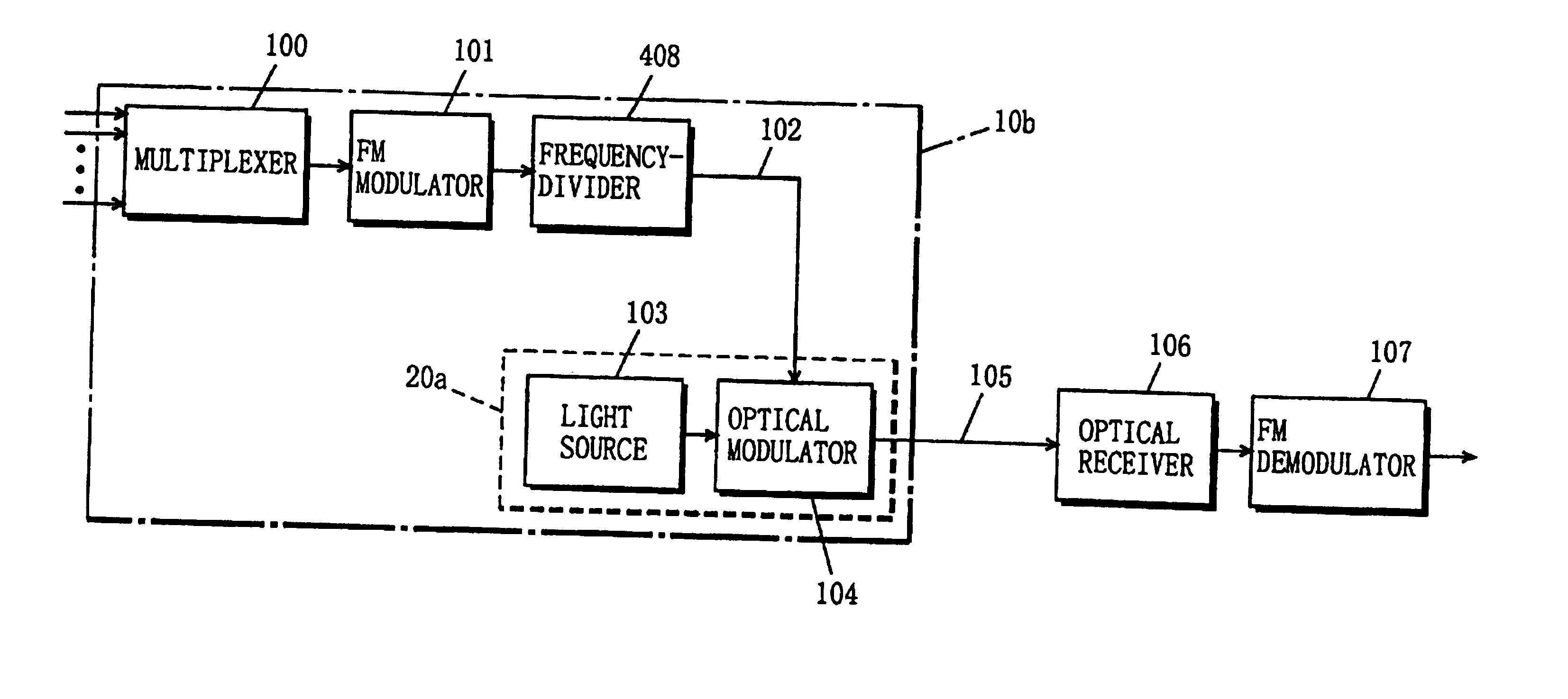
Figure 1 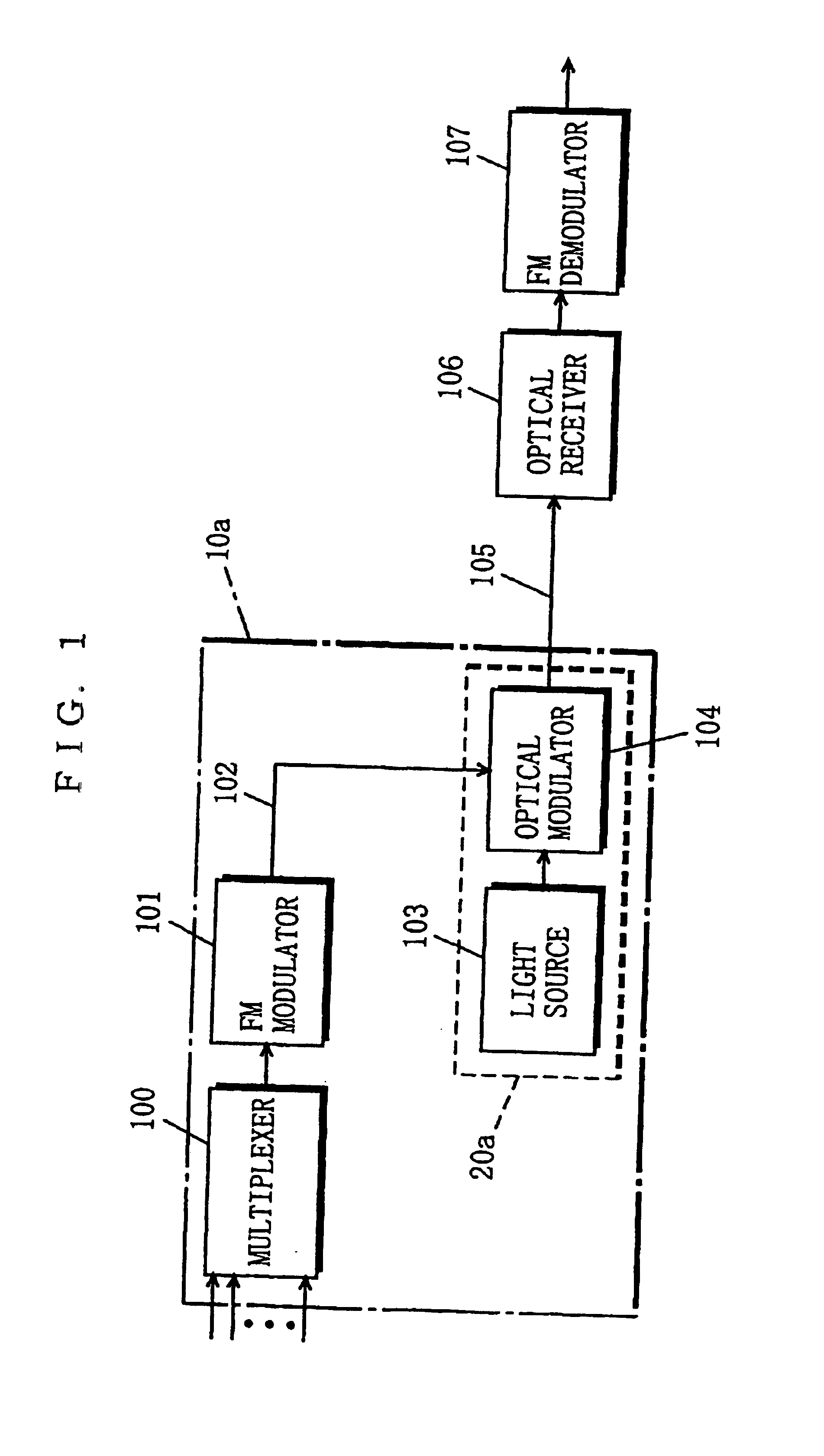
Figure 2 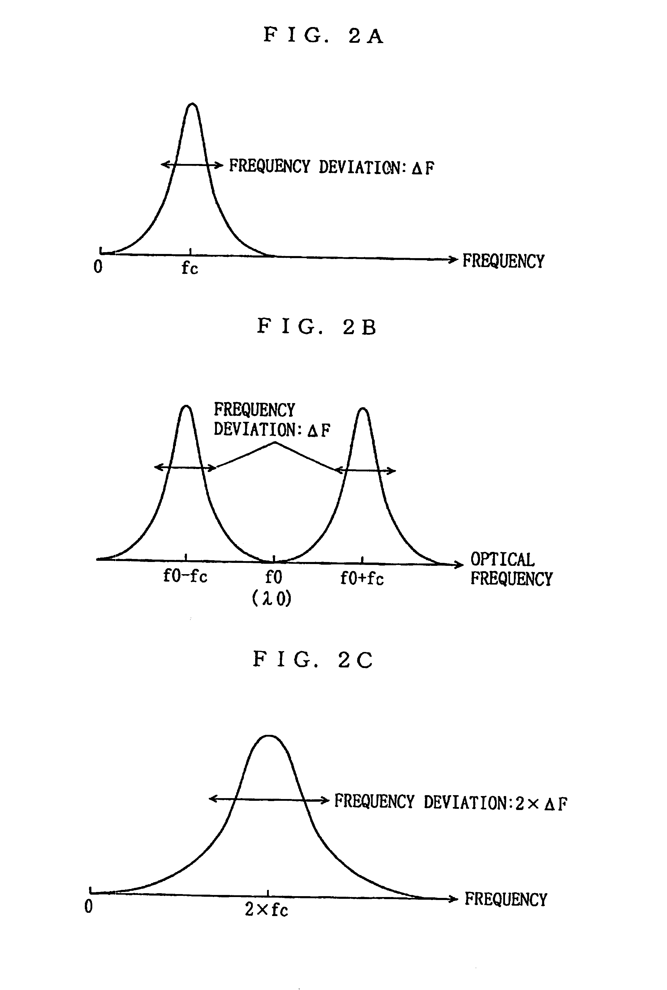
Figure 3
Abstract
Description
[0001] This application is a reissue application of U.S. Pat. No. 6,486,986, issued Nov. 26, 2002.BACKGROUND OF THE INVENTION
[0002] 1. Field of the Invention
[0003] The present invention relates to optical transmission systems, and more particularly to a system that optically transmits a frequency-division-multiplexed signal obtained by frequency-division-multiplexing a plurality of signals.
[0004] 2. Description of the Background Art
[0005] FIG. 11 is a block diagram exemplarily showing the configuration of a conventional optical transmission system for transmitting a frequency-division-multiplexed signal. As will be known from FIG. 11, this optical transmission system comprises a multiplexer 1100, an FM modulator 1101, an optical transmitter 1104, an optical receiver 1106, and an FM demodulator 1107. In the optical transmission system, an electrical transmission line 1102 connects the FM modulator 1101 and the optical transmitter 1104 to each other, and an optical transmission line 1105 c...
Examples
first embodiment
[0055]FIG. 1 shows the configuration of a system for optically transmitting a frequency-division-multiplexed signal according to a first embodiment of the present invention. Referring to FIG. 1, the optical transmission system of the present embodiment comprises a multiplexer 100, an FM modulator 101, a light source 103, an optical modulator 104, an optical receiver 106, and an FM demodulator 107. In the optical transmission system, an electrical transmission line 102 connects the FM modulator 101 and the optical modulator 104 to each other, and an optical transmission line 105 connects the optical modulator 104 and the optical receiver 106 to each other. The optical transmission system transmits an optical signal, which is produced in a below described manner, from a transmitting end to a receiving end through the optical transmission line 105. At the transmitting end, the light source 103 and the optical modulator 104 constitute an optical transmitter 20a, and the optical transmit...
second embodiment
[0059]FIG. 4 shows the configuration of an optical transmission system of an FM modulated signal according to a second embodiment of the present invention. Referring to FIG. 4, the optical transmission system of the present embodiment comprises the multiplexer 100, the FM modulator 101, the light source 103, the optical modulator 104, the optical receiver 106, the FM demodulator 107, and a frequency-divider 408. In the optical transmission system, the electrical transmission line 102 connects the frequency-divider 408 and the optical modulator 104 to each other, and the optical transmission line 105 connects the optical modulator 104 and the optical receiver 106 to each other. The configuration of the second embodiment is different from that of the above-described first embodiment only in including the frequency-divider 408. Therefore, the constituents identical to those in the first embodiment are assigned the same reference numerals, and the description thereof is simplified herei...
third embodiment
[0066]FIG. 7 shows the configuration of an optical transmission system of an FM modulated signal according to a third embodiment of the present invention. Referring to FIG. 7, the optical transmission system of the present embodiment comprises the multiplexer 100, the FM modulator 101, the light source 103, the optical modulator 104, the optical receiver 106, the FM demodulator 107, and an amplitude controller 709. In the optical transmission system, the electrical transmission line 102 connects the amplitude controller 709 and the optical modulator 104 to each other, and the optical transmission line 105 connects the optical modulator 104 and the optical receiver 106 to each other. The configuration of the third embodiment is different from that of the first embodiment in including the amplitude controller 709. Therefore, the constituents identical to those of the first embodiment are assigned the same reference numerals, and the description thereof is simplified herein. The differ...