

Automatic focusing method for digital image pickup device
An automatic focusing and digital imaging technology, applied in focusing devices, image communication, components of color TVs, etc., can solve the problems of inability to focus accurately, the maximum value of boundary information cannot be accurately positioned, etc., and achieve the effect of accurate automatic focusing
- Summary
- Abstract
- Description
- Claims
- Application Information
AI Technical Summary
Problems solved by technology
Method used
Image

Examples
Embodiment Construction
[0049] The basic idea of the present invention is to calculate and record the boundary information value of each lens position during the movement of the lens of the digital image capture device, and judge the boundary information values of multiple lens positions adjacent to each lens position , to end the autofocus operation when certain conditions are met.
[0050]The present invention will be further described below in conjunction with the accompanying drawings and embodiments.
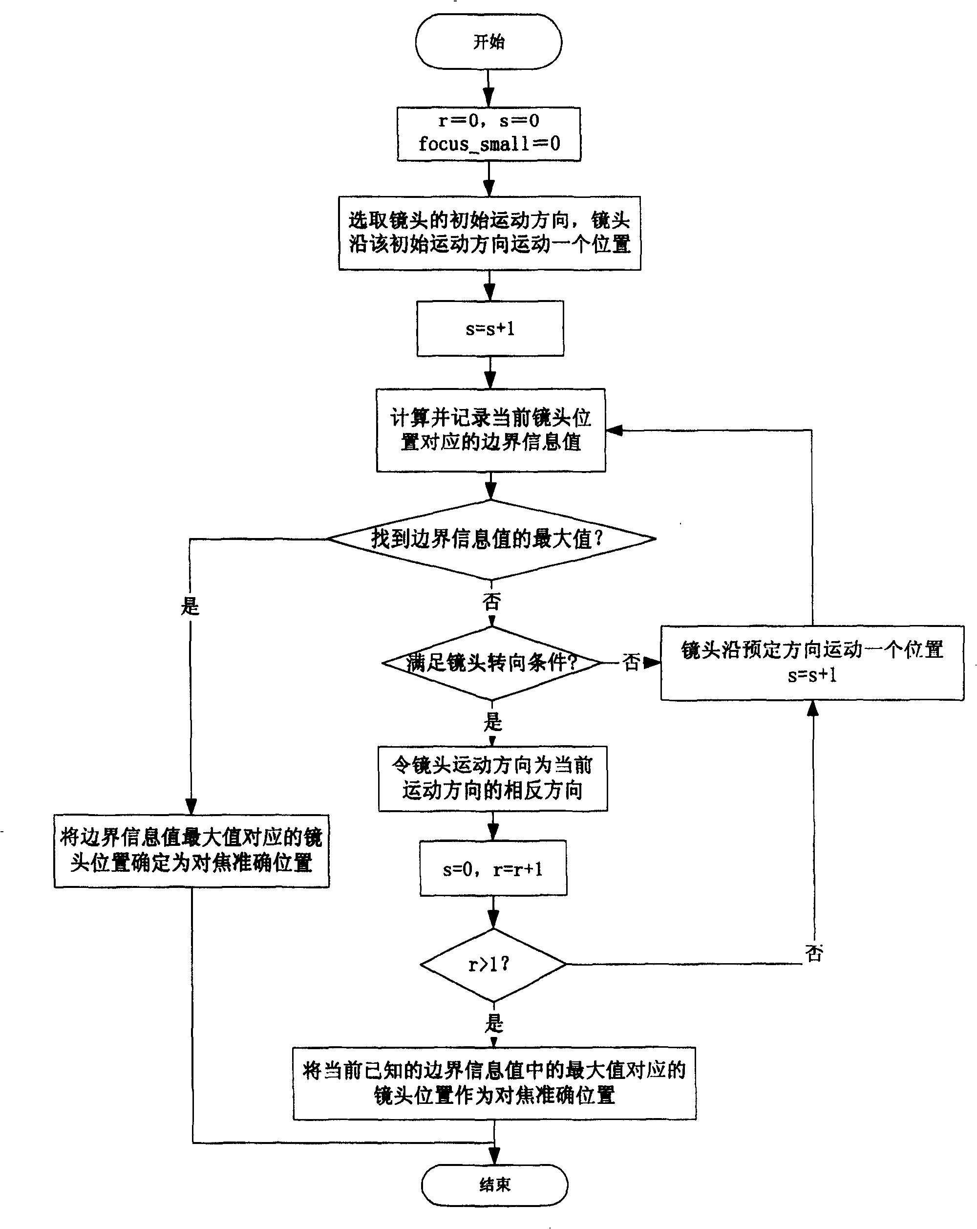
[0051] figure 1 It is a flowchart of the automatic focusing method of the present invention.
[0052] Such as figure 1 As shown, the autofocus method of the present invention comprises the following steps:
[0053] Step A: Select the initial movement direction of the lens, and the lens moves a position along this direction.
[0054] When the digital image capture device needs to perform autofocus, it first needs to select the initial movement direction of the lens. Assume that the total n...
PUM
 Abstract
Description
Claims
Application Information