
Automatic SUSAN focusing method for video monitoring system

A video surveillance system and auto-focusing technology, which is applied to parts of TV systems, parts of color TVs, TVs, etc., can solve the problem of incommensurate calculation amount and noise immunity, and achieve fast and accurate auto-focusing and real-time performance. The effect of good, good unimodality

Inactive Publication Date: 2015-04-22
CHANGCHUN INST OF OPTICS FINE MECHANICS & PHYSICS CHINESE ACAD OF SCI
View PDF5 Cites 0 Cited by
  • Summary
  • Abstract
  • Description
  • Claims
  • Application Information

AI Technical Summary

Problems solved by technology

[0005] The purpose of the present invention is to solve the problem that the current auto-focus algorithm calculation amount and noise resistance cannot be balanced, and propose a SUSAN auto-focus method for video surveillance systems

Method used


Image

  • Automatic SUSAN focusing method for video monitoring system
  • Automatic SUSAN focusing method for video monitoring system
  • Automatic SUSAN focusing method for video monitoring system

Examples


Embodiment 1

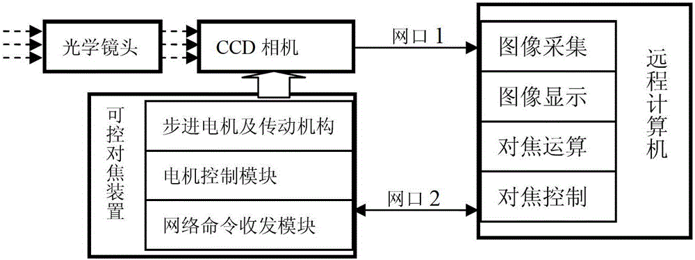
[0086] combine image 3 As shown, the embodiment of the present invention provides a SUSAN autofocus method for a video surveillance system, which is used to realize fast autofocus of a remote video surveillance system. The video monitoring system includes an optical lens, a CCD camera with a network interface, a remote computer and a controllable focusing device. Among them, the optical lens is a fixed-focus optical lens group that matches the optical parameters of the CCD camera, and its wavelength band ranges from 400nm to 700nm in the visible light band, and its focal length is 50mm. The CCD camera is a CM-140GE CCD industrial camera with a network interface from the Danish JAI company, which can realize remote transmission of image data through Ethernet. The remote computer is a PC or an industrial computer that can meet the CCD camera video acquisition, display and SUSAN auto focus calculation. The controllable focusing device includes a network command transceiver mod...

Embodiment 2

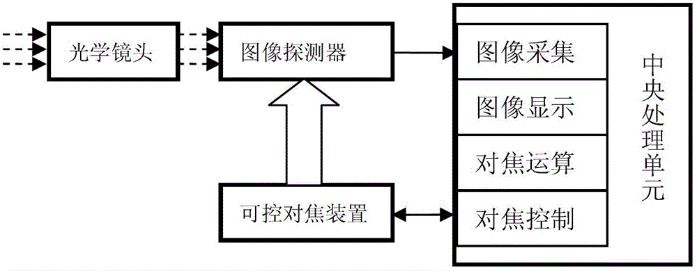
[0094] combine Figure 4 As shown, the embodiment of the present invention provides a SUSAN autofocus method for a video surveillance system, which is used to realize fast autofocus of a portable video surveillance device. The portable video monitoring system includes an optical lens, a CCD camera with a network interface, a central processing control board with image acquisition, display and processing functions, and a controllable focusing device. Among them, the optical lens is a fixed-focus optical lens group that matches the optical parameters of the CCD camera, and its wavelength band ranges from 400nm to 700nm in the visible light band, and its focal length is 50mm. The CCD camera is a Danish CM(B)-140MCL CCD industrial camera with a CameraLink interface, which can realize short-distance transmission of image data through the CameraLink data interface. The central processing control board is a control circuit board with ARM and DSP processing chips. DSP is used for im...


PUM


Abstract

The invention relates to an automatic SUSAN (Smallest Univalue Segment Assimilating Nucleus) focusing method for a video monitoring system, which is used for maintaining a position of an optical lens invariable, and adjusting a target surface position of an image detector to an optimal imaging position along an optical axis. The method comprises the following steps that an improved SUSAN edge extraction algorithm is adopted to serve as a definition evaluation function in an automatic focusing process, and an adaptive variable step size hill climbing algorithm is adopted to serve as an optimal definition value position searching algorithm in the automatic focusing process. As an SUSAN operator is improved to serve as the definition evaluation function in the automatic focusing process, the automatic SUSAN focusing method for the video monitoring system has good unimodality, unbiassedness and keenness, and also has good noise immunity and good real time. When the method is applied to automatic focusing in the video monitoring system, the automatic focusing of the system can be realized quickly and accurately.

Description

technical field [0001] The invention relates to an automatic focusing method for a video monitoring system, in particular to a SUSAN automatic focusing method for a video monitoring system. Background technique [0002] With the continuous development of electronic technology and image processing technology, robot vision and digital video systems have been widely used in daily life. Clear imaging is a basic requirement for video surveillance systems, and autofocus technology is an important prerequisite and guarantee for the system to obtain clear images. Therefore, autofocus technology has become a key technology for robot vision and digital video systems. The performance of the sharpness evaluation function will have a direct impact on the focusing effect of the video surveillance system, so the sharpness evaluation function should be selected reasonably according to the actual performance requirements of the system. The evaluation function with excellent performance shou...

Claims


Application Information

Patent Timeline
Patent Type & Authority Patents(China)
IPC IPC(8): G03B13/36G02B7/36H04N5/232
Inventor 张艳超赵建毕国玲曲锋
Owner CHANGCHUN INST OF OPTICS FINE MECHANICS & PHYSICS CHINESE ACAD OF SCI
Learn More