Fundus camera with auto focus

An autofocus and camera technology, applied in ophthalmoscopes, eye testing equipment, medical science, etc., can solve problems such as pupil constriction, fundus focusing, and difficulty in focusing time, and achieve the effect of reducing light stimulation and accurate autofocus

Active Publication Date: 2021-08-17
SHENZHEN SIBRIGHT TECH CO LTD
View PDF8 Cites 0 Cited by
  • Summary
  • Abstract
  • Description
  • Claims
  • Application Information

AI Technical Summary

Problems solved by technology

In the existing fundus cameras, a single visible light is usually used to directly collect fundus images. Visible light is good for lighting, so it can be used to collect images of the dark fundus. However, this single visible light fundus camera still has many shortcomings.
For example, because the eyes are more sensitive to visible light, when using visible light to collect fundus images and focus on the fundus, the eyes are easily stimulated by light, causing the pupils to shrink in a short time, and the focusing time is too short to make it difficult to accurately focus on the fundus

Method used


Image

  • Fundus camera with auto focus
  • Fundus camera with auto focus
  • Fundus camera with auto focus

Examples


Embodiment Construction

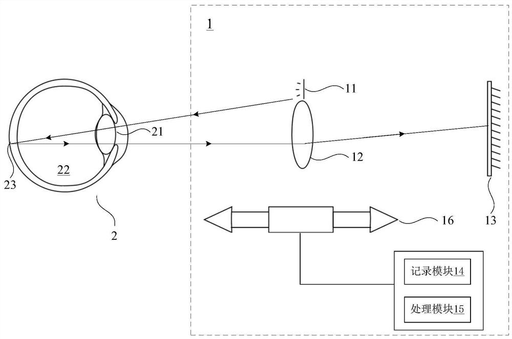
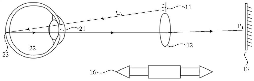
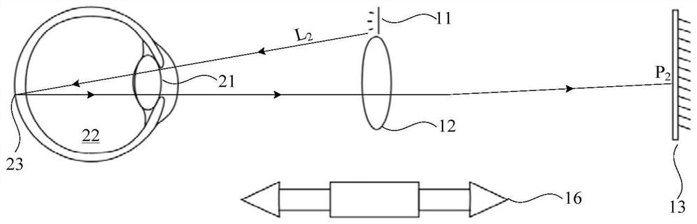
[0023] Hereinafter, preferred embodiments of the present disclosure will be described in detail with reference to the drawings. In the following description, the same reference numerals are given to the same components, and repeated descriptions are omitted. In addition, the drawings are only schematic diagrams, and the ratio of dimensions between components, the shape of components, and the like may be different from the actual ones.

[0024] It should be noted that the terms "comprising" and "having" and any variations thereof in the present disclosure, such as a process, method, system, product or device that includes or has a series of steps or units, are not necessarily limited to the clearly listed instead, may include or have other steps or elements not explicitly listed or inherent to the process, method, product or apparatus.

[0025] In addition, subheadings and the like involved in the following description of the present disclosure are not intended to limit the co...


PUM


Abstract

The present disclosure relates to an autofocus fundus camera, which includes: a light source for emitting a first light beam and a second light beam to the fundus of the eye, the first light beam is a light beam insensitive to the eye; a lens assembly; an imaging element for Receive the first light beam and the second light beam passing through the lens assembly; a recording module, which is used to record the first focus position when the first light beam is focused on the imaging element; a processing module, which is based on the wavelength of the first light beam and the diopter of the lens assembly Obtain the diopter of the eyeball with the first focus position, and obtain the second focus position after the second beam passes through the lens assembly based on the wavelength of the second light beam, the diopter of the eyeball and the diopter of the lens assembly; and the driving mechanism, which is based on the second focus The position adjusts the relative position between the lens assembly and the imaging element. According to the present disclosure, the fundus can be accurately auto-focused when the fundus image is collected, and the light stimulation to the eyes can be effectively reduced during the focusing process.

Description

technical field [0001] The present disclosure relates to an autofocus fundus camera. Background technique [0002] With the development of ophthalmic medical care, doctors can diagnose whether the subject suffers from fundus diseases by observing the fundus such as the retina, optic disc, and blood vessel distribution. At present, in clinical practice, doctors and the like usually use a fundus camera to collect fundus images of human eyes to observe the fundus. [0003] The fundus camera can emit a beam of light to the fundus through the pupil, and receive the reflected beam to image the fundus. In the existing fundus cameras, a single visible light is usually used to directly collect fundus images. Visible light is good for lighting, so it can be used to collect images of the dark fundus. However, this single visible light fundus camera still has many shortcomings. . For example, since the eyes are more sensitive to visible light, when using visible light to collect fund...

Claims


Application Information

Patent Timeline
Patent Type & Authority Patents(China)
IPC IPC(8): A61B3/12A61B3/15
CPCA61B3/12A61B3/152
Inventor 陈志陈大伟龚明利钟灿武
Owner SHENZHEN SIBRIGHT TECH CO LTD
Why Eureka
Try Eureka