System and method for providing a compact, flat, microwave lens with wide angular field of regard and wideband operation

a microwave lens and wide angular field technology, applied in the direction of antennas, antenna details, antenna adaptation in movable bodies, etc., can solve the problems of reducing the system thickness of a luneburg-derived lens, producing thick, heavy, bulky systems, etc., and achieves low cost, low volumetric depth, and high instantaneous bandwidth

Pending Publication Date: 2018-06-28
ALL SPACE NETWORKS LTD
View PDF5 Cites 89 Cited by
  • Summary
  • Abstract
  • Description
  • Claims
  • Application Information

AI Technical Summary

Benefits of technology

[0013]There is a need for a new type of antenna system that overcomes the limitations of mechanically steered antennas and electronically steered phased arrays, has high instantaneous bandwidth not limited by metamaterials or other highly dispersive structures, and is cost effective. Such an antenna system would have some or all of the following features: (a) low height profile, ideally appearing with lower volumetric depth and not requiring the protruding feeds of conventional reflectors; (b) electronically steerable beams with no moving parts; (c) capable of economically forming simultaneous multiple, independently steerable beams; (d) generally wide field of regard with beam steering over a large angular range from the aperture normal axis in any direction (depending on the application, an angular field of regard between 45 and 70 degrees is commonly required); and (e) cost structure that is substantially lower than conventional phased arrays with the typical half-wavelength element spacing, especially when considering multiple beams.

Problems solved by technology

Existing lenses, such as the Luneburg, produce systems that are thick, heavy, and bulky.
Transformation Optics techniques have been used to reduce the system thickness of a Luneburg-derived lens, but with limited success.

Method used


Image

  • System and method for providing a compact, flat, microwave lens with wide angular field of regard and wideband operation
  • System and method for providing a compact, flat, microwave lens with wide angular field of regard and wideband operation
  • System and method for providing a compact, flat, microwave lens with wide angular field of regard and wideband operation

Examples


example embodiments

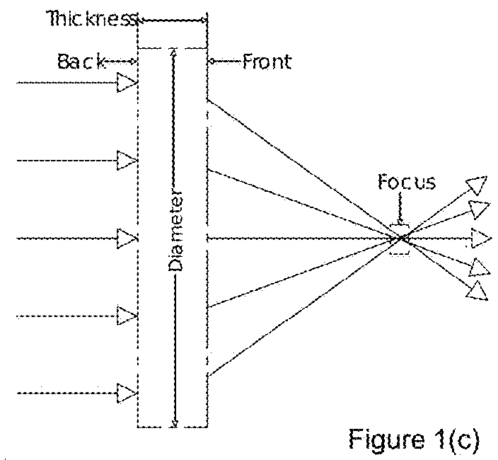
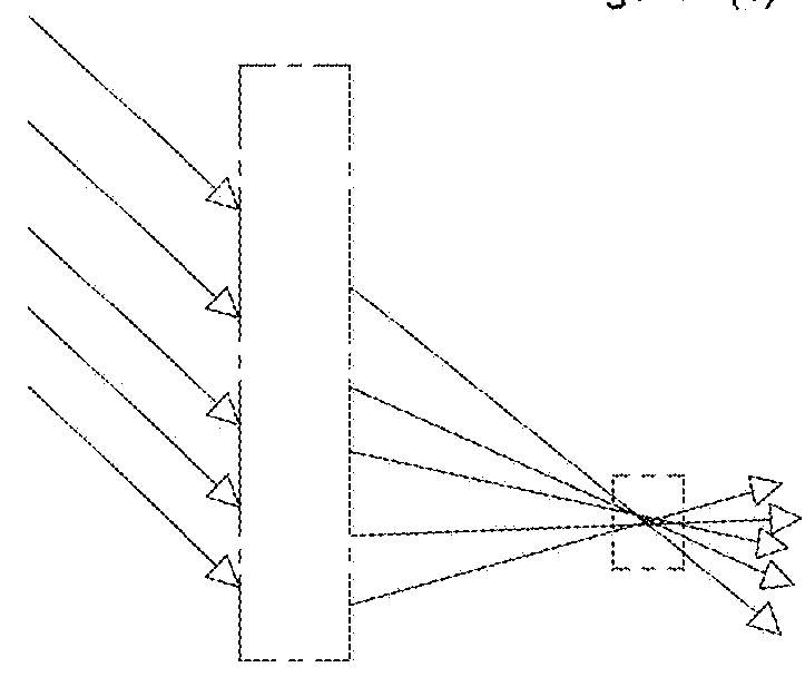
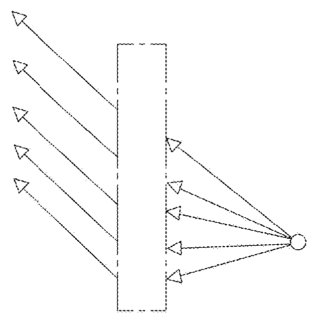
[0093]An electrically small lens (about 5λ or five wavelengths where λ is the wavelength) is suitable for use as an array element for a phased array of such lenses having far fewer active elements compared with a conventional phased array. The optimization process described above is executed in order to design a suitable candidate design. See FIG. 4 for the lens geometry.

[0094]The first steps of the design process are for the user to select the performance goals 154, geometric and material constraints 146, and design variables and constraints 101. The selections for the present example embodiment are as follows.

[0095]Performance goals (step 154): the lens is designed for Ku-band operation at 12 GHz, and is desired to have better than −5 dB aperture efficiency for all beams formed within a cone with apex angle (or, field of regard) of 45 deg. The peak directivity for a 100% efficient aperture in dB is given by the equation: Directivitymax,DB=10*log10(4*pi*A / lambda2). For a lens with ...


PUM


Abstract

A system designs a thin and relatively flat microwave focusing lens that can produce multiple simultaneous beams, using readily-available isotropic dielectric materials, and having a gradient-index (GRIN) profile. The design optimizes the lens to achieve beam scanning and/or multiple beams over a wide field of regard (FOR) with broad bandwidth and a very short focal length compared with conventional lenses. The lens can be used individually or as an element in a more complex antenna having multiple lenses in various orientations that are independently switched, selected and/or excited simultaneously as elements in a phased array. The antenna terminal incorporates such lens into an array of lenses along with one or more feeds to produce single or multiple beams covering a broad field of regard for such applications as satellite communications on-the-move, cellular, broadband point-point or point-multipoint and other terrestrial or satellite communications systems. The lens and array design support multiple simultaneous independently steerable beams as well as null placement for interference cancellation.

Description

RELATED APPLICATIONS[0001]This application claims the benefit of U.S. Provisional Application No. 62 / 438,181, filed Dec. 22, 2016, the entire contents of which are incorporated herein by reference.BACKGROUND OF THE INVENTIONField of the Invention[0002]The present invention relates to a system and design method that provides low-profile, thin dielectric lens antennas that have wide-angle beam steering with one or more feed elements, and that can be used with associated electronics for beam pointing control, and hardware and software interfaces with receive and transmit subsystems, allowing simultaneous one-way or two-way communications with one or more satellites or other remote communication nodes.Background of the Related Art[0003]Many types of antenna and terminal systems exist today for fixed installations and satellite communications (SATCOM) on-the-move (SOTM) applications. Examples include DIRECTV 3LNB Ka Ku Slim Line Dish Antenna (solidsignal.com), DISH Network Triple LNB HD ...

Claims


Application Information

Patent Timeline
Patent Type & Authority Applications(United States)
IPC IPC(8): H01Q15/02H01Q1/28H01Q19/06H01Q1/48
CPCH01Q15/02H01Q1/288H01Q19/062H01Q1/48H01Q25/008H01Q15/08G06F30/20
Inventor TURPIN, JEREMIAH P.SCARBOROUGH, CLINTON P.DIFONZO, DANIEL F.FINNEY, JOHN
Owner ALL SPACE NETWORKS LTD
Why Eureka
Try Eureka