Automatic focusing method for digital image pickup device

An auto-focus and digital imaging technology, applied in focusing devices, image communication, color TV components, etc., can solve problems such as inability to focus accurately, and inaccurate positioning of the maximum value of boundary information, to achieve accurate auto-focus effects

Inactive Publication Date: 2007-03-14
VIMICRO CORP
View PDF1 Cites 1 Cited by
  • Summary
  • Abstract
  • Description
  • Claims
  • Application Information

AI Technical Summary

Problems solved by technology

[0009] However, this method is only applicable in an ideal state, that is, only when there is only one peak in the boundary information value curve, that is, when the left side of the peak rises monotonously and the right side monotonically decreases, the maximum value of the boundary information value can be accurately fo

Method used


Image

  • Automatic focusing method for digital image pickup device

Examples


Embodiment Construction

[0048] The basic idea of ​​the present invention is to calculate and record the boundary information value of each lens position during the movement of the lens of the digital image capture device, and judge the boundary information values ​​of multiple lens positions adjacent to each lens position , to end the autofocus operation when certain conditions are met.

[0049] The present invention will be further described below in conjunction with the accompanying drawings and embodiments.

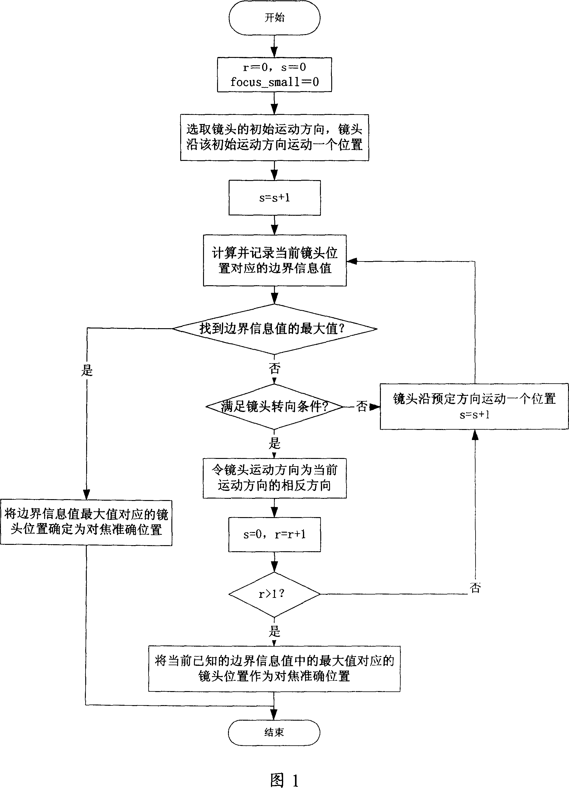
[0050] FIG. 1 is a flow chart of the autofocus method of the present invention.

[0051] As shown in Figure 1, the autofocus method of the present invention comprises the following steps:

[0052] Step A: Select the initial movement direction of the lens, and the lens moves a position along this direction.

[0053] When the digital image capture device needs to perform autofocus, it first needs to select the initial movement direction of the lens. Assume that the total number of lens posit...


PUM


Abstract

The auto focusing method for a digital image acquisition device comprises: A. selecting the initial movement direction for lens, let it move to a position; let r = 0 and s = 1; B. calculating and recording corresponding boundary information of current lens position; C. deciding whether it has found out the maximal value of information value; if yes, determining current lens position as the accurate focus position, the process ends; D. if meeting lens deflecting condition, let lens movement direction as the inverse one for current movement, let s = 0 and r = r+1; E. if r>1, taking lens position with known maximal boundary information value as the focusing position, the process ends; F. moving lens along preset direction, let s = s+1, and turning to step B.

Description

technical field [0001] The invention relates to an automatic focusing method of an image capture device, in particular to an automatic focus method of a digital image capture device. Background technique [0002] A patent document whose publication number is CN1794032 discloses an autofocus method, comprising the following steps: a) acquiring the image data of the initial position of the lens and extracting the edge of the image, counting the pixel values ​​of each point on the edge to obtain the boundary and store the information value, and store the corresponding lens position at the same time; b) move the lens, and obtain the boundary information value of the image corresponding to the current lens position according to the method described in step a); c) compare the boundary information value of the current image with the above For the boundary information values ​​stored once, save the larger value and its corresponding lens position, and then perform steps b) and c) in...

Claims


Application Information

Patent Timeline
IPC IPC(8): G03B13/36H04N5/225
Inventor 卢虹
Owner VIMICRO CORP
Why Eureka
Try Eureka