Auto-focus apparatus and method

Active Publication Date: 2018-11-06
BEIJING SPREADTRUM HI TECH COMM TECH CO LTD
View PDF13 Cites 0 Cited by
  • Summary
  • Abstract
  • Description
  • Claims
  • Application Information

AI Technical Summary

Benefits of technology

[0041]Firstly, the present disclosure provides an auto-focus apparatus, and the focus control module therein is different from existing focus control modules in focusing mechanism. Specifically, in the present disclosure, a frequency respond result of interested pixels in an original image is used as focusing statistics. The frequency respond result can be used for selecting an effective frequency band, where the effective frequency band indicates a focusing accuracy. Furthermore, through driving the lens to diffident positions, multiple original images are obtained. Based on frequency respond results corresponding to these multiple original images, a desired frequency respond result is selected, thus a first lens position corresponding to the desired frequency respond result is taken as a focusing position. According, an accurate auto-focusing is achieved by moving the lens to the focusing position.
[0042]Accordingly, the focusing statistic information (i.e. the frequency respond results) used in the auto-focusing process implemented by the auto-focus apparatus of the present disclosure is more stable. Specifically, image data are processed from aspect of frequency domain, which are less likely to be influenced by factors such as ambient light, etc. Further, the focus control module in the auto-focus apparatus is adapted to filter image noise and extract precise focus statistic data. Accordingly, focusing performance is improved.
[0043]Secondly, through the auto-focus method provided by the presen

Problems solved by technology
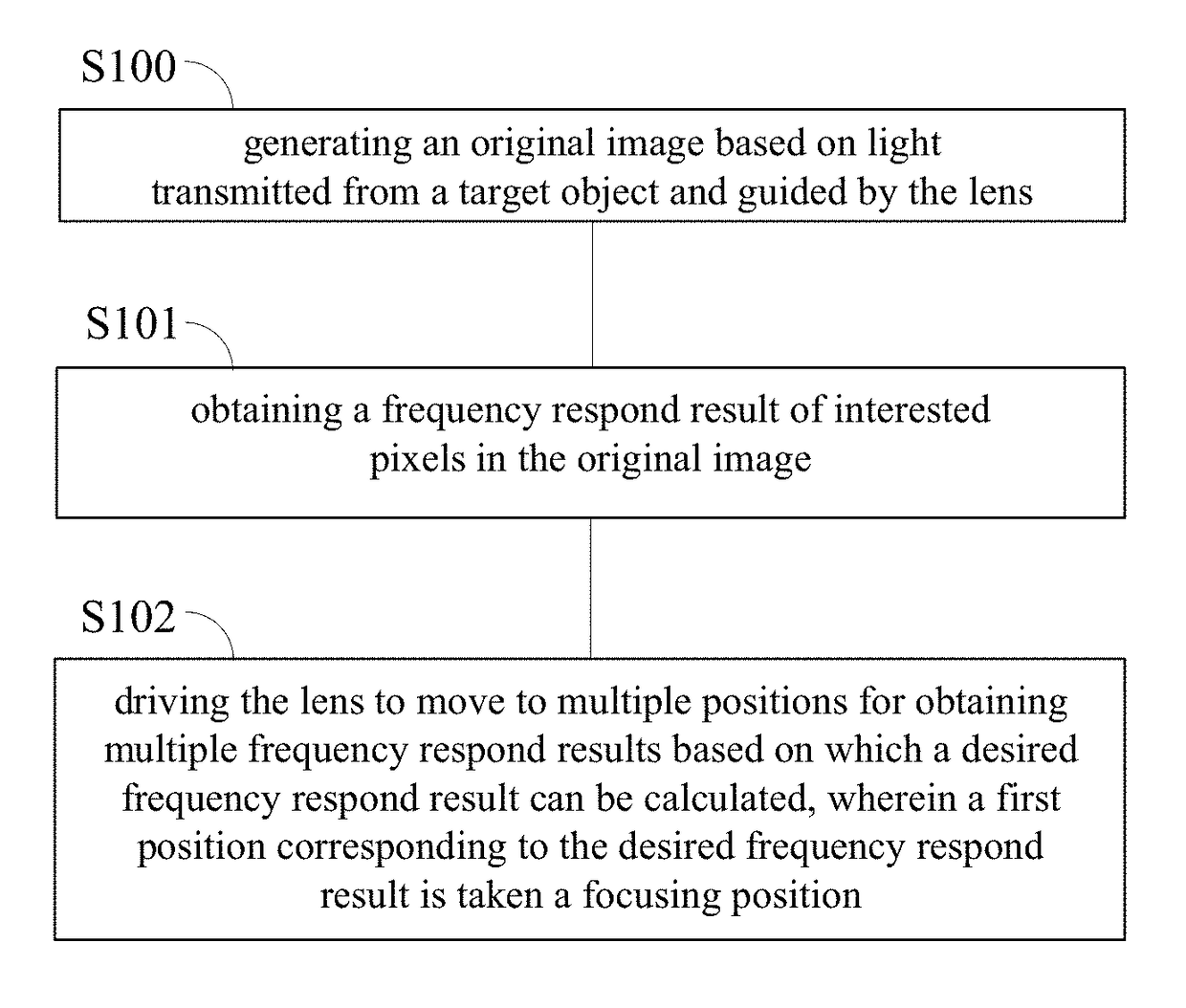
Especially when the target object has a slanted surface or a smooth surface, auto-focusing performance of the photographic equipment may be degraded.
Further, when the target object has high brightness and is far away from the photographic equipment, it may be difficult to achieve auto-focusing.
Thus, it may be hard to achieve auto-focusing when the ambient light is weak.
Accordingly, the light may be reflected by the glass, and focusing

Method used


Image

  • Auto-focus apparatus and method
  • Auto-focus apparatus and method
  • Auto-focus apparatus and method

Examples


Embodiment Construction

[0056]In order to clarify the objects, characteristics and advantages of the present disclosure, embodiments of the present disclosure will be described in detail in conjunction with the accompanying drawings. The disclosure will be described with reference to certain embodiments. Accordingly, the present disclosure is not limited to the embodiments disclosed. It will be understood by those skilled in the art that various changes may be made without departing from the spirit or scope of the disclosure.

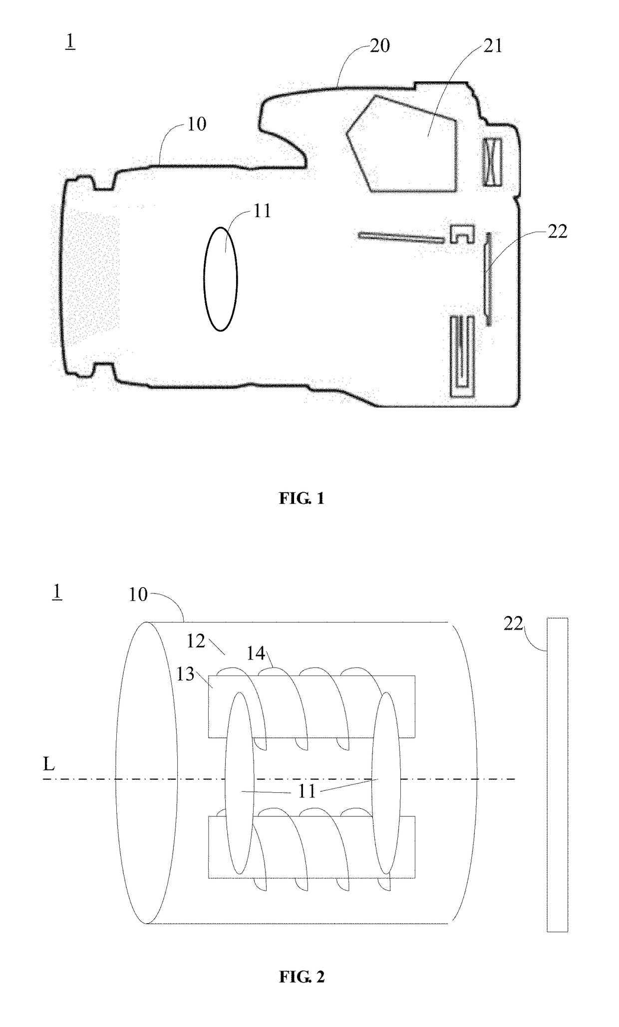
[0057]Referring to FIG. 1, a piece of photographic equipment according to one embodiment of the present disclosure is illustrated. The photographic equipment may be a camera module of a cell phone or a camera. The photographic equipment includes a lens system 10 and a main apparatus 20. The main apparatus 20 is configured to obtain image data of a target object based on light guided by the lens system 10.

[0058]In combination with referring to FIG. 2, the lens system 10 includes a lens ...


PUM


Abstract

An auto-focus apparatus and an auto-focus method are provided. The auto-focus apparatus includes: a lens, a lens driving component, and a focus control module; wherein the lens is configured to guide light transmitted from a target object; wherein the lens driving component is configured to drive the lens to move to the multiple positions to obtain the original images, and drive the lens to a focusing position obtained by the focus control module; and wherein the focus control module is configured to obtain frequency respond results each of which corresponds to interested pixels in one of the original images, calculate a desired frequency respond result based on the obtained frequency respond results and take a first position of the lens corresponding to the desired frequency respond result as the focusing position. Accordingly, focus accuracy and focus speed under conditions of poor contrast texture and weak light are improved.

Description

CROSS-REFERENCE TO RELATED APPLICATIONS[0001]The present application claims priority to Chinese patent application No. 201410827420.7, filed on Dec. 25, 2014, and entitled “AUTO-FOCUS APPARATUS AND METHOD”, the entire disclosure of which is incorporated herein by reference.TECHNICAL FIELD[0002]The present disclosure generally relates to imaging field, and more particularly, to an auto-focus apparatus and an auto-focus method.BACKGROUND[0003]Usually, a piece of photographic equipment, such as a camera, a cell phone configured with a photographing function, etc., is able to implement auto-focusing.[0004]Auto-focusing is achieved by utilization of light reflection. Specifically, light reflected by a target object (i.e. an object being photographed) is caught by an imaging sensor (such as, a CCD sensor, a CMOS sensor, etc.) of the photographic equipment. Information corresponding to the reflected light is further processed by a computer for actuating a power focus apparatus, so as to ac...

Claims


Application Information

Patent Timeline
IPC IPC(8): H04N5/232G03B13/36G03B30/00
CPCH04N5/23212H04N23/67
Inventor HU, YIWANG, HAOWANG, WEI
Owner BEIJING SPREADTRUM HI TECH COMM TECH CO LTD
Why Eureka
Try Eureka