Bulb type fluorescent lamp and illuminator

A technology of self-ballasting and fluorescent lamps, which is applied to lighting devices, components of lighting devices, and cooling/heating devices of lighting devices. Effects of lowering temperature, uniform pressure inside the lamp, and ensuring ventilation

Inactive Publication Date: 2010-02-17
TOSHIBA LIGHTING & TECH CORP
View PDF8 Cites 1 Cited by
  • Summary
  • Abstract
  • Description
  • Claims
  • Application Information

AI Technical Summary

Problems solved by technology

However, if the distance between the housing and the edge of the substrate is long, the substrate cannot be placed sufficiently on the cap side, and the substrate becomes larger on the side of the arc tube, and when it is not at the edge of the substrate facing the housing, In the case of arranging wiring patterns and electronic components, etc., in order to arrange the wiring patterns and electronic components, it is necessary to increase the substrate on the side of the arc tube, so the area of ​​the substrate on the arc tube side is larger than the area on the cap side, so the size of the cover is relatively small. difficulty

Method used


Image

  • Bulb type fluorescent lamp and illuminator
  • Bulb type fluorescent lamp and illuminator
  • Bulb type fluorescent lamp and illuminator

Examples


Embodiment Construction

[0064] Hereinafter, embodiments of the present invention will be described with reference to the drawings.

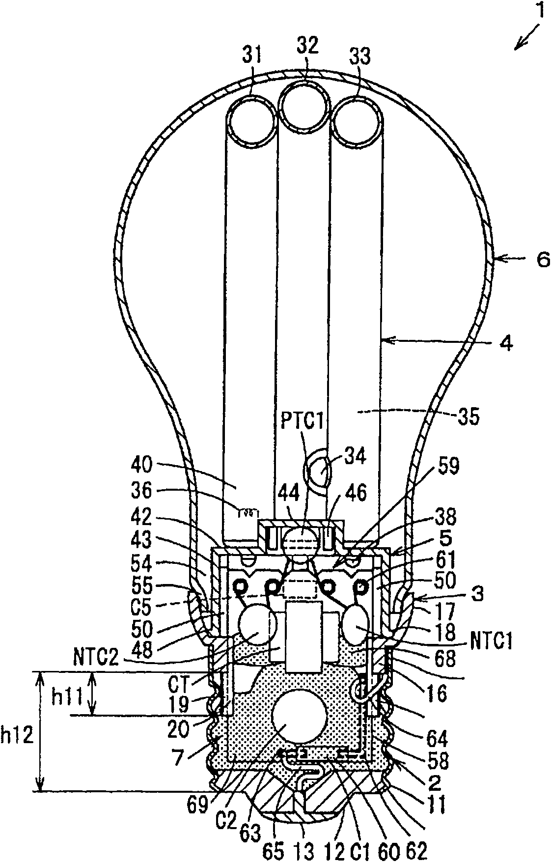
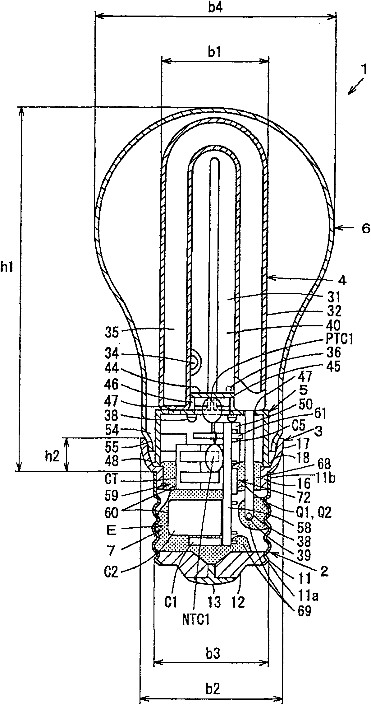
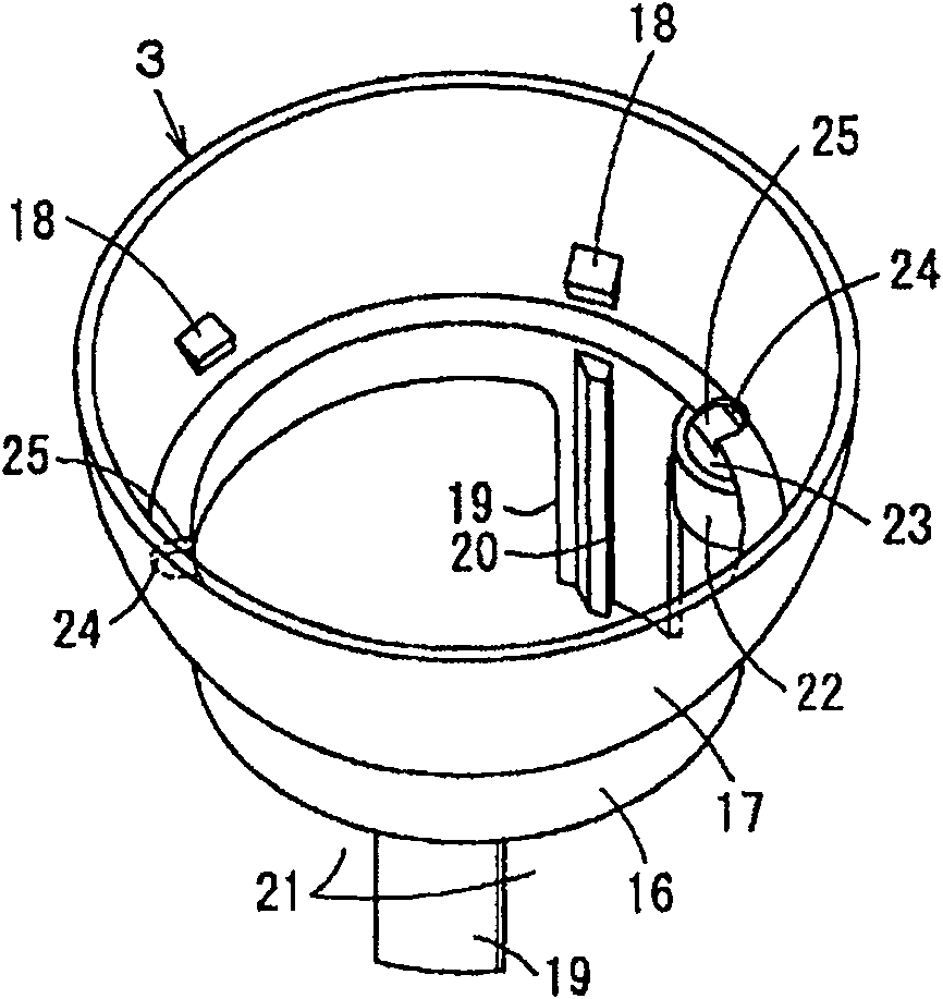
[0065] Figure 1 to Figure 13 1st Embodiment is shown. figure 1 It is a cross-sectional view when viewed from a direction intersecting the direction in which glass bulbs of a compact self-ballasted fluorescent lamp are arranged side by side, figure 2 It is a cross-sectional view of a small self-ballasted fluorescent lamp viewed from the direction in which glass bulbs are arranged side by side. image 3 is a perspective view of the housing of a small self-ballasted fluorescent lamp, Figure 4 It is a partial cross-sectional view of the cover body of a small self-ballasted fluorescent lamp, Figure 5 It is a cross-sectional view showing the positional relationship between the bracket of the small self-ballasted fluorescent lamp, the luminous tube and the substrate, Image 6 is a perspective view of a bracket for a small self-ballasted fluorescent lamp, Figure 7 It...


PUM


Abstract

The present invention provides a self-ballasting fluorescent lamp (1) which can obtains an external appearance that is approximate same to the common illuminating electric bulb and reduces the heat influence of the luminous tube (4) to the electronic component (60) that is configured at the inner side of the lamp holder (2). One end side of the cover body (3) is arranged with a lamp holder (2) andthe other end side of the cover body (3) is supported with a luminous tube (4). The substrate (58) of the lighting device (7) is installed with an electronic component (60) of the light circuit (59)which lights the luminous tube (4). The substrate (58) is formed to a breadth dimension that can be inserted in the inner side of the lamp holder (2) and is longitudinally arranged along the center line direction of the lamp holder (2), the cover body (3) is minimized to obtain an external appearance approximately same to the common illuminating electric bulb. The heat insulating material (64) isarranged at the opening between the longitudinally arranged substrate (58) and the cover body (3). The heating insulating material (64) is used for insulating the heat between the side of the lamp holder (2) and the side of luminous tube (4) and reducing the heat influence of the luminous tube (4) to the electronic component (60) arranged at the inner side of the lamp holder (2). At the inner sideof the lamp holder (2) the front end part of the tubule (38) enveloped with main mercury alloy (39) is thermally connected with one part of electronic component (60) and the lamp holder (2) by the heat conducting material (65).

Description

technical field [0001] The present invention relates to a small self-ballasted fluorescent lamp having an arc tube and a lighting device for lighting the arc tube, and an illuminating device using the small self-ballasted fluorescent lamp. Background technique [0002] Conventionally, a small self-ballasted fluorescent lamp has: a light-emitting tube having a curved bulb; a cover having a lamp cap attached to one end and supporting the light-emitting tube at the other end; a lighting device accommodated in the cover; On the other end side of the cover body, it covers the globe of the luminous tube and the like. [0003] In recent years, this small self-ballasted fluorescent lamp is being miniaturized to the lamp length and maximum outer diameter defined in JIS (Japanese Industrial Standards, Japan Industrial Standards), which are close to those of ordinary lighting bulbs. The proportion and the maximum outer diameter of the cover body are larger. Therefore, the appearance ...

Claims


Application Information

Patent Timeline
Patent Type & Authority Patents(China)
IPC IPC(8): F21S2/00F21V23/00F21V29/00F21Y103/025F21V29/15F21Y103/37
Inventor 筏邦彦田中敏也小林胜之久保田洋白田伸弥中村真理河野仁志
Owner TOSHIBA LIGHTING & TECH CORP
Why Eureka
Try Eureka