Cabin type helix transporting device

A technology of screw conveying device and screw conveyor, which is used in conveying bulk materials, conveyors, transportation and packaging, etc., can solve the problems of blockage of the discharge port, high energy consumption and pipeline blockage.

Active Publication Date: 2008-06-25
FUJIAN LONGKING
View PDF1 Cites 10 Cited by
  • Summary
  • Abstract
  • Description
  • Claims
  • Application Information

AI Technical Summary

Problems solved by technology

However, after adopting this structure, since the screw conveyor and the lower hopper are connected by pipelines, it is easy to cause the discharge port in the lower hopper to be blocked. The limestone powder from the pipe to the conveying pipe consumes a lot of energy and is more likely to cause pipe blockage

Method used


Image

  • Cabin type helix transporting device
  • Cabin type helix transporting device
  • Cabin type helix transporting device

Examples


Embodiment Construction

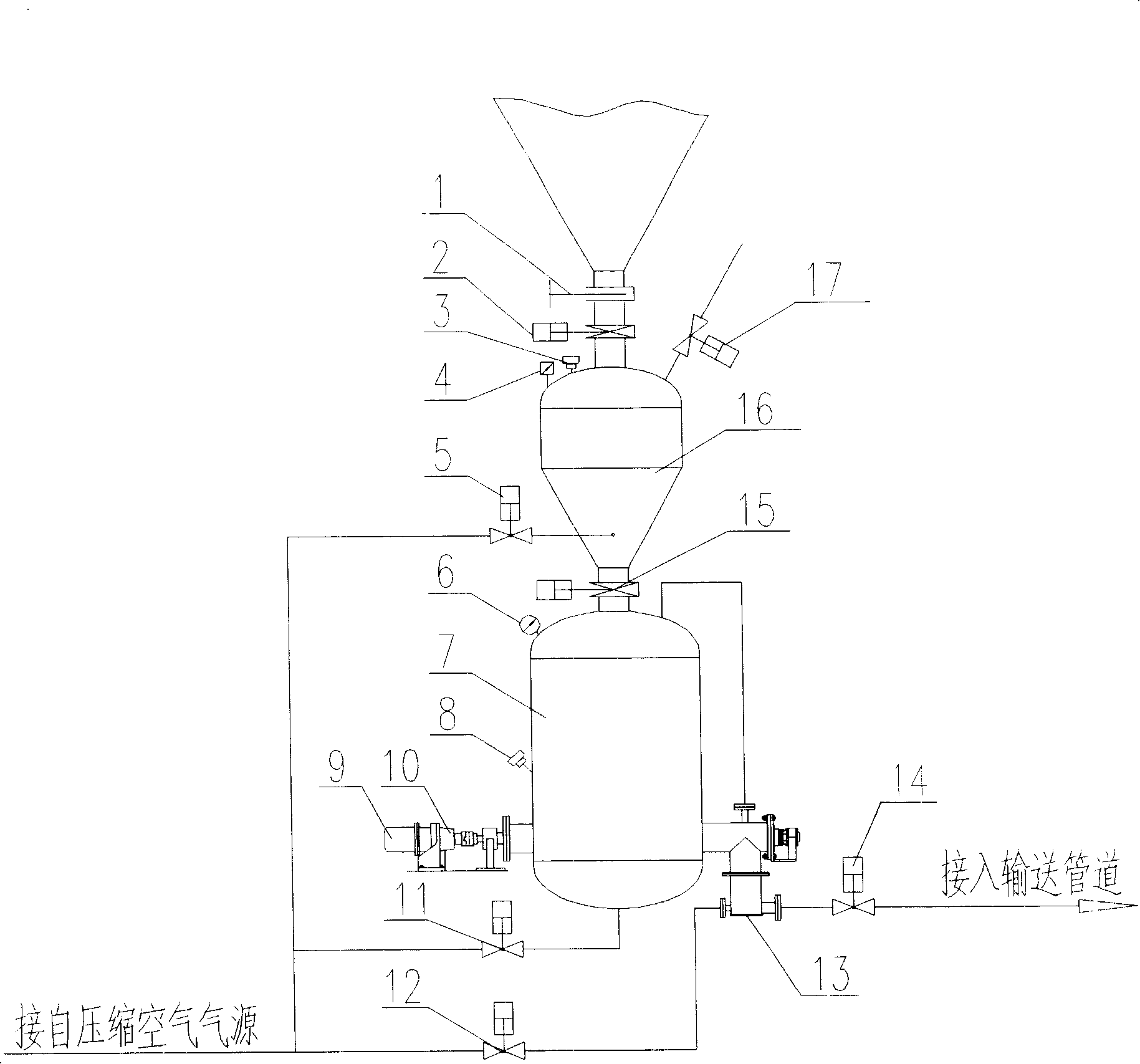
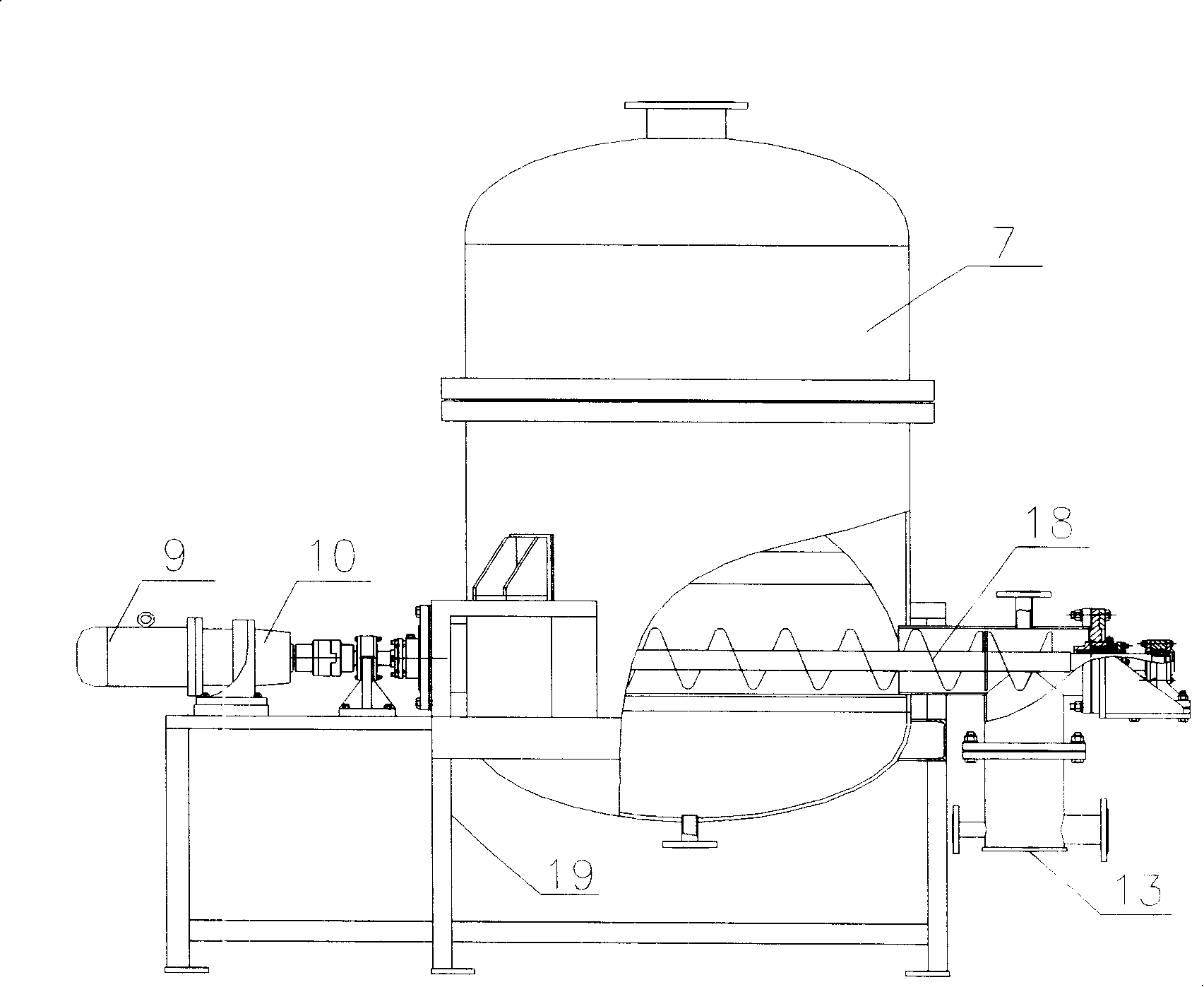
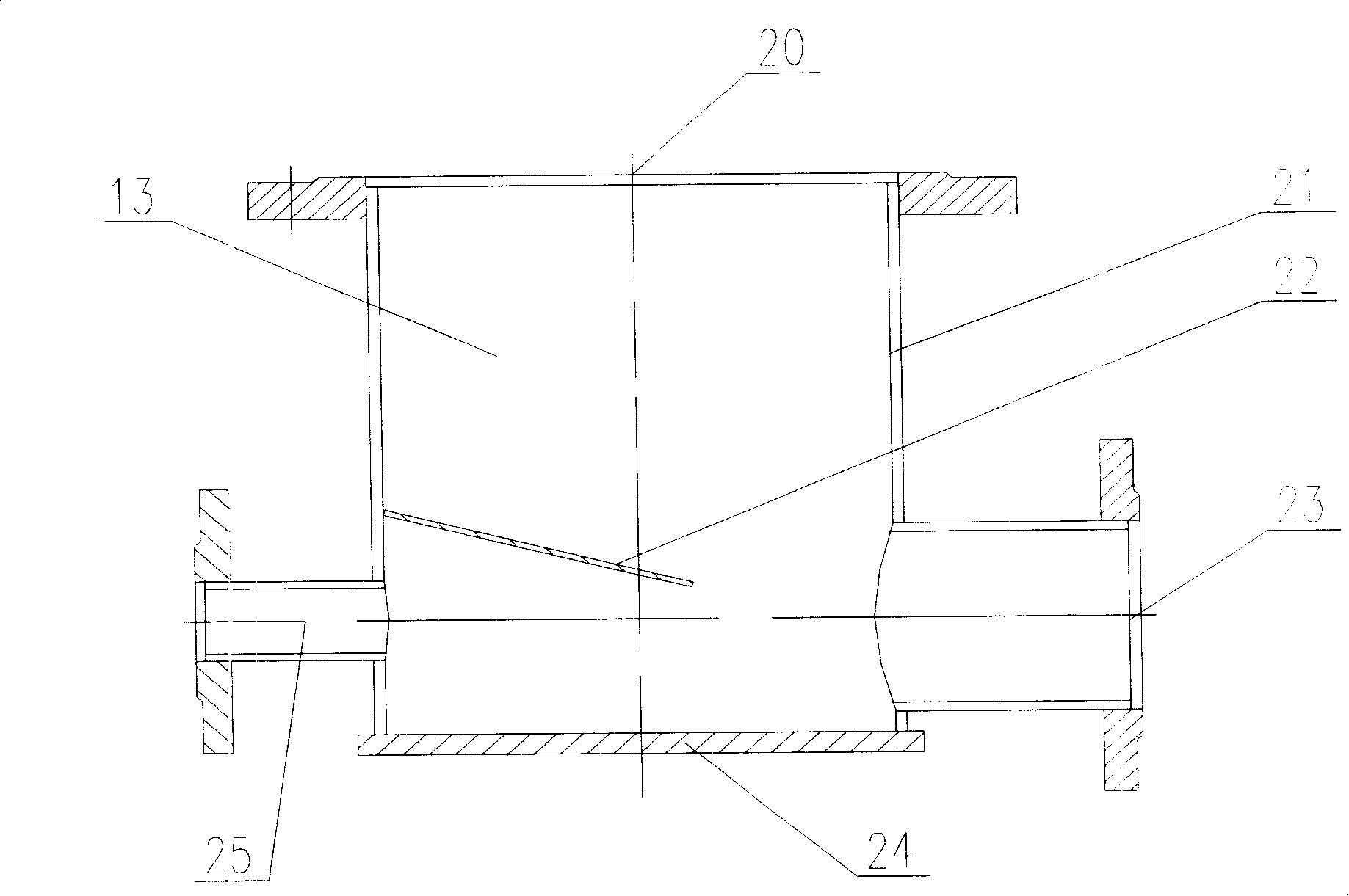
[0014] figure 1 As shown, the warehouse-type screw conveying device is composed of a silo, an upper hopper (16), a lower hopper (7), a screw conveyor (18) and a frame (19), and the upper hopper (16) is arranged on the lower hopper (7). ), the feed bin is arranged above the upper hopper (16); figure 2 As shown, the lower hopper (7) is arranged on the frame (19), the screw conveyor (18) is placed in the lower hopper (7), and the discharge port of the screw conveyor (18) and the gas mixing chamber (13) The feed port (20) of the feed gas mixing chamber (13) is respectively provided with an air inlet (25) and a feed outlet (23) at the bottom of the feed gas mixing chamber (13). The air connection, the material gas mixing chamber (13) outlet (23) is connected with the conveying pipeline; the motor (9) and the reducer (10) that make the screw conveyor (18) rotate are arranged outside the lower hopper (7). on the shelf (19); image 3 As shown, the feed gas mixing chamber (13) is c...


PUM


Abstract

The invention discloses a spiral delivery device of storehouse type to solve the problems of easy pipe blocking and high energy consumption in the prior device. The invention adopts a spiral conveyor (18) installed in a lower hopper (7). A discharge hole of the spiral conveyor (18) is connected with an inlet orifice (20) of a material and gas mixing cavity (13). An air inlet (25) and a discharge orifice (23) are respectively arranged at the lower part of the material and gas mixing cavity (13). The air inlet (25) of the material and gas mixing cavity (13) is connected with compressed air. The discharge orifice (23) of the material and gas mixing cavity (13) is connected with a delivery pipe. Therefore, the invention has the advantages of few occurrences of blockage and can reduce energy consumption.

Description

Technical field [0001] The invention relates to a material conveying device, in particular to a bin-type screw conveying device composed of a silo, an upper hopper, a lower hopper, a screw conveyor and a frame. Background technique [0002] Chinese Patent Publication No. CN1704647A discloses such a calcium spraying pneumatic conveying system in front of the furnace, and its structural characteristics are: [0003] It is composed of a silo, an upper hopper, a lower hopper, a screw conveyor and a fan. The upper hopper is set above the lower hopper, and the upper hopper communicates with the lower hopper. The outlet of the screw conveyor is connected with the feed port of the screw conveyor, the discharge port of the screw conveyor is connected with a vertically arranged drop pipe through a horizontal conveying pipe, the air outlet of the fan is connected with one end of an air pipe, and the air pipe The other end is connected to the inlet end of a delivery pipe, and the lower...

Claims


Application Information

Patent Timeline
Patent Type & Authority Applications(China)
IPC IPC(8): B65G53/16B65G53/48B65G53/36B65G53/34B65G65/46B65D88/54
Inventor 曹强利倪奕金苏金辉陈胜飞袁礼江兴涛
Owner FUJIAN LONGKING
Why Eureka
Try Eureka