
Automatic testing method for mixer third order inter-modulation distortion of radio-frequency tuner chip
A technology of radio frequency tuning and third-order intermodulation, applied in electronic circuit testing, instruments, spectrum analysis, etc., can solve the problems of high test cost and long test time, and achieve the goal of reducing test cost, improving test efficiency and ensuring test accuracy. Effect
- Summary
- Abstract
- Description
- Claims
- Application Information
AI Technical Summary
Problems solved by technology
Method used
Image

Examples
Embodiment Construction
[0026] The present invention will be further described in detail below in conjunction with the accompanying drawings and specific embodiments.
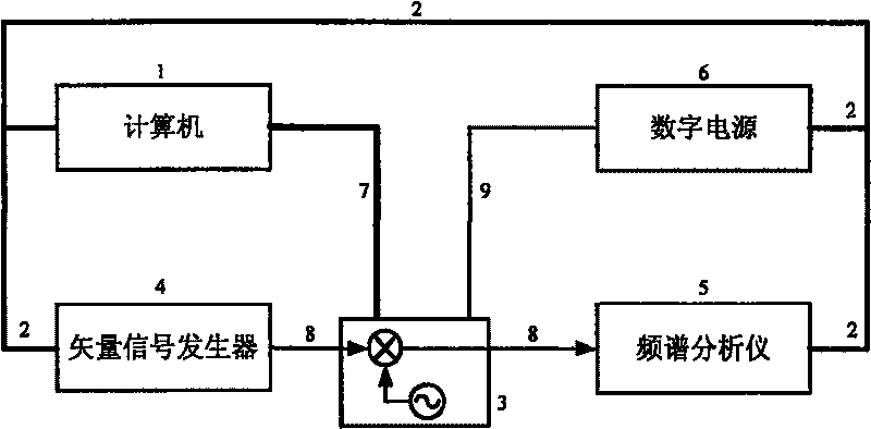
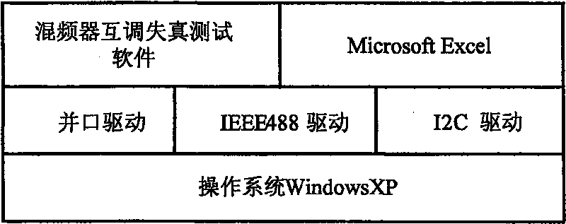
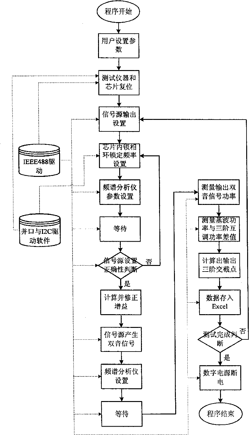
[0027] The framework of the proposed automated testing method for third-order intermodulation distortion of mixers in RF tuner chips is shown in figure 1 As shown, it is composed of main control computer, Agilent GPIB connection module 82357A, chip under test, Agilent E4438C vector signal generator, Agilent E4402B spectrum analyzer, Agilent E3649A digital power supply, parallel port connection line, RF connection line and power supply connection line ; Install the IEEE488 driver on the main control computer, and connect the Agilent E4438C vector signal generator, Agilent E4402B spectrum analyzer and Agilent E3649A digital power test instrument in parallel through the Agilent USB to GPIB port connection module 82357A, each instrument has a specific The address is convenient for host addressing; the main control computer is connected to...
PUM
 Abstract
Description
Claims
Application Information