Fleece-laying apparatus

A fiber web and web laying machine technology, which is applied to the fiber web laying machine, can solve problems such as complex routes, and achieve the effect that is easy to achieve

Inactive Publication Date: 2008-10-01
DILO MASCHF OSKAR
View PDF1 Cites 17 Cited by
  • Summary
  • Abstract
  • Description
  • Claims
  • Application Information

AI Technical Summary

Problems solved by technology

[0004] The result of this is that the two card web belts have a very complex course with many turning points in the upper and laying carriages

Method used


Image

  • Fleece-laying apparatus

Examples


Embodiment Construction

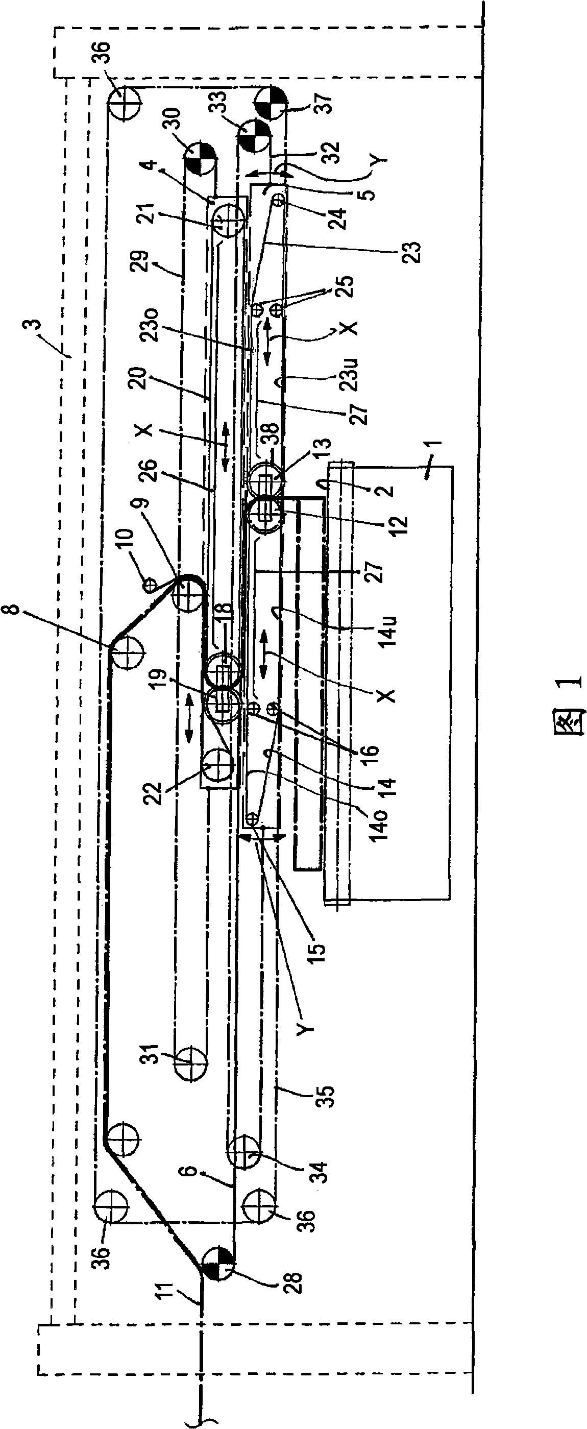
[0021] Accompanying drawing represents the schematic diagram of fiber web lapper, and shown lapper comprises:

[0022] - the output conveyor belt 2 , which is supported on the lower table 1 , is schematically represented by its deflection guide rollers and is designed, for example, as a slatted belt;

[0023]- an upper carriage 4 which is movable within the (schematically represented) frame 3 transversely to the conveying direction of the output conveyor belt 2; and

[0024] - The laying carriage 5 , which is movable below the upper carriage transversely to the output conveyor belt 2 .

[0025] In the example shown, the conveyor belt carrying the card web (hereinafter referred to as the card web inlet conveyor belt 6 ) passes the upper carriage 4 , which conveyor belt runs past a plurality of deflection guide rollers supported in the frame 3 . The card web inlet conveyor belt 6 does not pass through the laying carriage 5, but passes over it. Optionally, the upper carriage 4 ...


PUM


Abstract

In a fleece layer of the carriage cross-lapper type, the laying carriage conveyor belt ( 14 ) wraps around the first laying roller ( 12 ), the upper and lower strands ( 14 o, 14 u) of the belt being parallel to each other as they proceed from the first laying roller ( 12 ). An endless cover belt ( 23 ), which travels around in the laying carriage ( 5 ), wraps around the second laying roller ( 13 ), the cover belt having upper and lower strands ( 23 o, 23 u), which are parallel to each other as they proceed from the second laying roller ( 13 ) in the direction opposite that of the laying carriage conveyor belt ( 14 ). The mutual distances between the web entrance ( 8, 9 ), the upper carriage ( 4 ), the laying carriage ( 5 ), and the output conveyor belt ( 2 ) perpendicular to the transport directions of same are so small that the card web ( 11 ) to be laid is enclosed in a sandwich-like manner between the adjacent strands of the web entrance conveyor belt ( 6 ), of the upper carriage conveyor belt ( 20 ), and of the laying carriage conveyor belt ( 14 ), where the laid fleece on the output conveyor belt ( 2 ) is contacted by the laying carriage conveyor belt ( 14 ) and by the cover belt ( 23 ).

Description

technical field [0001] The invention relates to a fiber web lapper of the carriage crosslapper type, having a fixed fiber web inlet, an upper carriage and a laying carriage in which endless conveyor belts run, respectively, and laying guide rollers, A laying gap is formed between the laying guide rollers to convey the card web to be laid onto an output conveyor belt, above which two carriages are movably guided in the machine frame transversely to the conveying direction of the belt . Background technique [0002] A fiber web laying machine of the aforementioned type is disclosed in "Vliesstoffe" (Nonwoven Fabrics) by W. Albrecht, H. Fuchs and W. Kittelmann, published by WILEY-VCH, Weinheim, 2000, p. 161 . The advantage of this type of web laying machine is that the running path of the conveyor belt involved in the card web transport is very simple. However, the path of the card web through the lapper is open, and the laying of the web on the output conveyor is likewise op...

Claims


Application Information

Patent Timeline
Patent Type & Authority Applications(China)
IPC IPC(8): D01G25/00D01G23/00D04H1/00
CPCD01G25/00
Inventor 约翰P·迪罗
Owner DILO MASCHF OSKAR
Why Eureka
Try Eureka