Multi-wing sail polar exploration robot

A technology of robot and installation mechanism, which is applied in the field of detection robot to achieve the effect of simple control, flexible robot movement and sufficient power source

Active Publication Date: 2017-01-11
SHANGHAI UNIV
View PDF8 Cites 0 Cited by
  • Summary
  • Abstract
  • Description
  • Claims
  • Application Information

AI Technical Summary

Problems solved by technology

[0005] After reviewing the existing domestic and foreign literature, it is found that the existing methods of utilizing wind energy are mainly wind power generation technology, but the existing wind power generation technology is generally only applicable to the wind speed range of 4m / s to 16m / s (when the wind speed is too high, usually control The conversion efficiency is generally less than 30%, while the average wind speed in Antarctica is high, 20m / s-30m / s is a common wind speed, the deeper the Antarctic inland, the stronger the wind, and due to the harsh environment of Antarctica, the robot needs The driving power is often 5 to 10 times the normal required power

Method used


Image

  • Multi-wing sail polar exploration robot
  • Multi-wing sail polar exploration robot
  • Multi-wing sail polar exploration robot

Examples


Embodiment 1

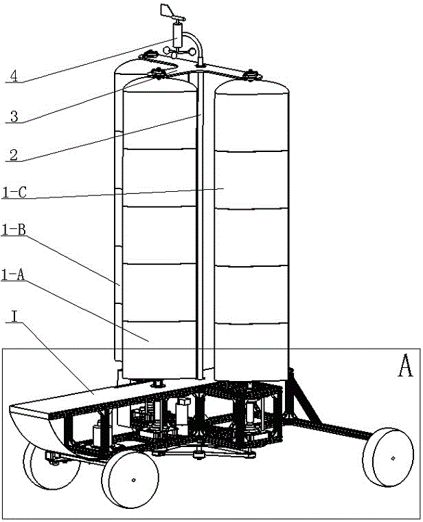
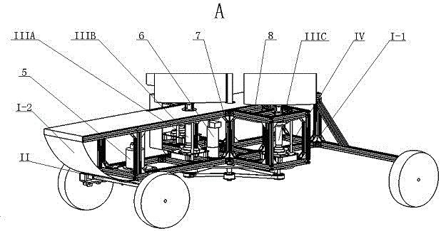
[0028] refer to Figure 1 ~ Figure 3 , the multi-wing sail polar detection robot, which includes a hull I, a front wheel steering mechanism II, a wing sail synchronous rotation mechanism IV, three wing sail rotation installation mechanisms IIIA, IIIB, IIIC, three wing sails 1-A , 1-B, 1-C, a bottom wing sail positioning plate 7, a middle wing sail positioning plate 8, a top wing sail positioning plate 3 and a wind direction anemometer 4. The front wheel steering mechanism II is a parallelogram mechanism, which is fixedly installed on the hull I with screws and T-shaped nuts, and the front wheel steering mechanism II is driven by the steering gear 5 to realize a multi-wing sail polar detection robot Turning movement around axis Z. The sails 1-A, 1-B, and 1-C are fixed to the sail rotation installation mechanisms IIIA, IIIB, and IIIC respectively through ring screw groups, and the sail rotation installation mechanisms IIIA, IIIB, and IIIC use keys and The shaft retaining ring ...

Embodiment 2

[0030] This embodiment is basically the same as Embodiment 1, and the special features are as follows:

[0031] The hull I is formed by screwing a hull I-1 and a hull I-2; according to the distribution characteristics of the word "product" of the airfoils 1-A, 1-B, and 1-C, The hull I-1 is a "ten"-shaped frame structure constructed of aluminum profiles, and the front end of the hull I-2 adopts an arc-shaped structure.

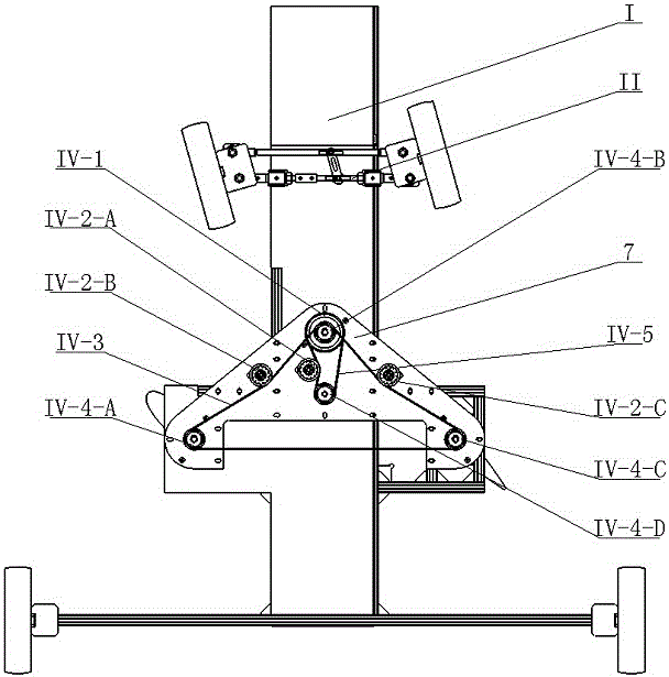
[0032] Said wing-sail synchronous rotation mechanism IV is: a small pulley IV-4-D connects a large pulley IV-1 through a short synchronous belt IV-5, and said large pulley IV-1 and a small pulley IV -4-B coaxial installation, the small pulley IV-4-B connects two small pulleys IV-4-A and IV-4-C through a long synchronous belt IV-3; the servo motor 6 drives The small pulley IV-4-D realizes the synchronous rotation of the large pulley IV-1 and the small pulleys IV-4-A, IV-4-B, and IV-4-C, that is, the sail Synchronous rotation between 1-A, 1-B, and 1-C; a tensio...

Embodiment 3

[0036] Such as figure 1 As shown, the hull I is formed by screwing a hull I-1 and a hull I-2; the hull I-1 is a "ten"-shaped frame structure constructed of aluminum profiles, It is easy to install the control system, power supply system and sensor system and can reduce its own mass. The robot has small inertia and good start-stop performance; the front end of the hull I-2 adopts an arc structure, and the air resistance is small when the robot moves forward.

[0037] A wind direction anemometer 4 is fixedly connected with the top wing sail positioning plate 3, and the wind direction anemometer 9 obtains the information of the ambient wind in real time, and feeds back to the control system to make the servo motor 6 drive the small pulley IV-4-D , the small pulley IV-4-D is connected to a large pulley IV-1 through a short synchronous belt IV-5, and the large pulley IV-1 is coaxially installed with a small pulley IV-4-B, so Described small pulley IV-4-B connects two small pulleys...


PUM


Abstract

The invention discloses a multi-wing-sail polar detection robot. The robot comprises a ship, a front wheel steering mechanism, a wing sail synchronous rotation mechanism, three wing sail rotation mounting mechanisms, three wing sails, three wing sail location plates and an aerovane. A steering engine drives the front wheel steering mechanism to achieve rotation of the multi-wing-sail polar detection robot around the axis Z. The wing sails are fixed on the wing sail rotation mounting mechanisms, the wing sail rotation mounting mechanisms fixed on the ship body are fixedly connected with the wing sail synchronous rotation mechanism, and the synchronous of the wing sails relative to the ship body is achieved through rotation of a servo motor. The middle wing sail location plate and the bottom end wing sail location plate are fixed with the ship body, and the top end wing sail location plate supporting the aerovane is fixedly connected with the wing sails in the Z direction. The robot is compact in structure, stable in moving, wide in moving range and long in endurance time.

Description

technical field [0001] The invention relates to the field of detection robots, in particular to a multi-wing sail polar detection robot. Background technique [0002] The multi-wing sail polar detection robot is a mobile robot directly driven by wind. The driving force of the robot movement is generated by the wind through multiple wing sails, so that the robot can move on the ice and snow surface to complete the polar detection. It has a wide range of activities and a long battery life. [0003] After reviewing the existing domestic and foreign literature, it is found that the existing polar exploration robots include crawler-type polar ice and snow mobile robots, spherical robots, and low-altitude fixed-wing flying robots, but most of them are powered by batteries or fuel engines, which are limited by the robot’s carrying capacity. However, due to the limitation of the number of batteries or fuel, the range of activities of these detection robots is still very limited, and...

Claims


Application Information

Patent Timeline
Patent Type & Authority Patents(China)
IPC IPC(8): B25J11/00
Inventor 谢少荣冯凯陈继清罗均吴翔程启兴
Owner SHANGHAI UNIV
Why Eureka
Try Eureka