Handling manipulator assembly

A manipulator component and manipulator technology, which is applied to manipulators, program-controlled manipulators, mechanical equipment, etc., can solve the problems of complex second variants, and achieve the effect of high mobility and stable structure

Inactive Publication Date: 2008-10-15
EROWA
View PDF3 Cites 62 Cited by
  • Summary
  • Abstract
  • Description
  • Claims
  • Application Information

AI Technical Summary

Problems solved by technology

While the fork on the first variant is only conditionally movable, the second variant with its two

Method used


Image

  • Handling manipulator assembly
  • Handling manipulator assembly
  • Handling manipulator assembly

Examples


Embodiment Construction

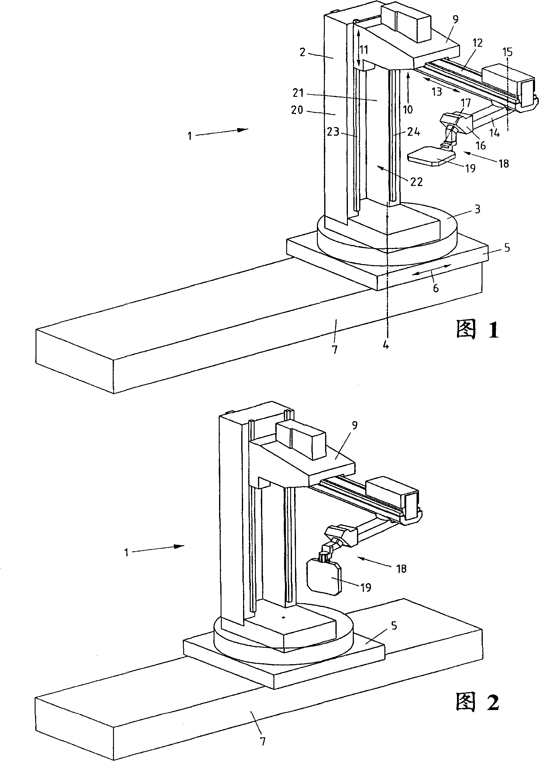
[0020] Referring now to FIG. 1 , there is illustrated an exemplary aspect of a manipulator assembly according to the present invention to explain its basic configuration. The manipulator assembly 1 comprises a vertical main support 2 placed on a turntable 3 . In the present embodiment, the main support 2 is positioned centrally on the turntable 3, however it could also be positioned off-centre. A turntable 3 rotating around a vertical axis 4 is secured to a horizontally traveling main slide 5 which can travel on a slide 7 as indicated by the double arrow 6 . A vertical slide 9 designed for vertical travel is placed on the vertical main support 2 . Here again, the direction of travel of the vertical slide 9 is indicated by a double arrow 11 . The vertical carriage 9 comprises a stable support body 9 a, on the underside 10 of which is arranged a horizontal extension arm 12 designed for horizontal travel, the direction of travel of which is likewise indicated by a double arrow ...


PUM


Abstract

The assembly (1) has a vertically extending main support (2) rotatable about a vertical axis (4), and a horizontal extension arm (12) supported by a vertically traveling vertical carriage on the vertical main support. A manipulator gripper (18) is supported directly or indirectly on the horizontal extension arm, which is supported on the vertical carriage for horizontal travel by a linear guide. The horizontal extension arm is provided with an articulated arm (14) rotatable about a vertical axis (15), the manipulator gripper arranged at the end of the articulated arm. Independent claims are also included for the following: (1) a method for feeding/removing workpieces and/or tools to/from a machine tool (2) a machine tool assembly including a machine tool.

Description

technical field [0001] The invention relates to a handling manipulator assembly as stated in the preamble of claim 1 and also to the use of a handling manipulator assembly as stated in claim 15 and to the Machine tool components. Background technique [0002] For automatically feeding or removing workpieces from machine tools such as lathes, milling machines, die-cutting machines, punching tools, operating assemblies such as manipulators are known. In addition to being used for feeding / removing workpieces, these operating assemblies can of course also be used for feeding / removing tools. [0003] A generic manipulator assembly is known from EP-A-1 481759 . This assembly features a horizontal entry over which the first carriage can travel horizontally. The first slide is provided with an elongated support on which the other slide can travel vertically. An arm designed to pivot about a horizontal axis is mounted on the first carriage. A workpiece handling gripper is secure...

Claims


Application Information

Patent Timeline
IPC IPC(8): B25J3/00B25J18/04B25J19/00B23Q7/04
CPCB25J9/041Y10T74/20335B23Q7/04B23Q7/1494
Inventor B·桑德迈耶
Owner EROWA
Why Eureka
Try Eureka