Ultrasound treatment system

a treatment system and ultrasonic technology, applied in the field of ultrasonic treatment system, can solve the problems of deteriorating maneuverability, limited clamping area, and insufficient force applied to the region, and achieve the effects of reducing the need for check work, and reducing the need for arousal of impedan

Inactive Publication Date: 2010-08-24
OLYMPUS CORP
View PDF28 Cites 332 Cited by
  • Summary
  • Abstract
  • Description
  • Claims
  • Application Information

AI Technical Summary

Benefits of technology

[0034]An object of the present invention is to provide an ultrasound treatment system in which a treatment unit of an ultrasound treatment appliance can turn relative to a manipulating means and the ultrasound treatment appliance can therefore be used under endoscopic observation or the like with good maneuverability in the same manner as a surgical appliance.
[0042]Still another object of the present invention is to provide an ultrasound treatment system contributing to further improvement of maneuverability and a drastic reduction in time required for a surgery.

Problems solved by technology

For avoiding these incidents, time-consuming and annoying check work is needed.
This becomes one of causes deteriorating maneuverability.
This poses problems that a clamped area is limited and sufficient force is not applied to a region to be cut out.
In particular, for example, as far as a ligament containing lots of fibers is concerned, there is a problem that the ligament cannot be cut off reliably, or a problem that since it takes much time to perfectly cut off the ligament, a surgical blade may dissipate heat very much to burn any other living tissue in contact with the surgical blade.
Since there is a structural restriction that the probe cannot be turned because the center axis of the probe does not align with the center axis of a conveying means, an ultrasound treatment appliance in which a treatment unit can be turned freely relative to a manipulating means is unavailable.
Thus, the ultrasound treatment appliance still has drawbacks that must be overcome for practical use.
However, in this appliance, since a handpiece serving as a manipulating means is circular and devoid of directivity, good maneuverability is ensured.
In an ultrasound treatment appliance having a directive handle as a manipulating means, the aforesaid problems cannot be solved completely.
This work is quite laborious and cumbersome.
However, there is a problem, which must be solved, concerning the reduction of medical expenses, diminishment of polluted wastes, and saving of resources.
However, the appliance becomes large in size and expensive.
The cautery knife has the hazard of a leakage current.
Moreover, since the cautery knife and ultrasound knife are different from each other in terms of medical functions and advantages, they may not sometimes be acted simultaneously.
When compared with an ultrasonic suction apparatus having a very simple intra-sheath structure, the intra-sheath structure of the ultrasonic coagulation / incision system is very complex.
Once blood or a fatty tissue sucked into the sheath adheres to the inside of the probe, it is very hard to remove the blood or fatty tissue.
Consequently, the ultrasonic coagulation / incision system fails to ultrasonically oscillate.
Specifically, the impedance characteristic of the probe is disordered, and the resonant frequency of a resonant circuit becomes uncertain.
This poses a problem in that the ultrasonic coagulation / incision system cannot ultrasonically oscillate any longer.
There is a fear that a living tissue other than the intended living tissue may be affected by the heat.
However, a region that must not be affected by heat may be sunk in a fatty tissue or hidden behind a treatment portion.
In this case, the region may not be able to be observed.
Furthermore, if a region susceptible to heat and the treatment portion are located mutually closely, ultrasonic treatment cannot be conducted.
This poses a problem in that usable ultrasonic treatment appliances are limited.
In this case, an unbearable abnormal sound may be heard.
This hinders observation of a surgical field.
Moreover, the endoscope itself is clouded.
This poses a serious problem.
This is time-consuming.
Since the work cannot be carried on continuously, a long time is required for a surgery.
Besides, a patient load is enormous.

Method used


Image

  • Ultrasound treatment system
  • Ultrasound treatment system
  • Ultrasound treatment system

Examples


first embodiment

[0184]Referring to FIGS. 3 to 11, the present invention will be described.

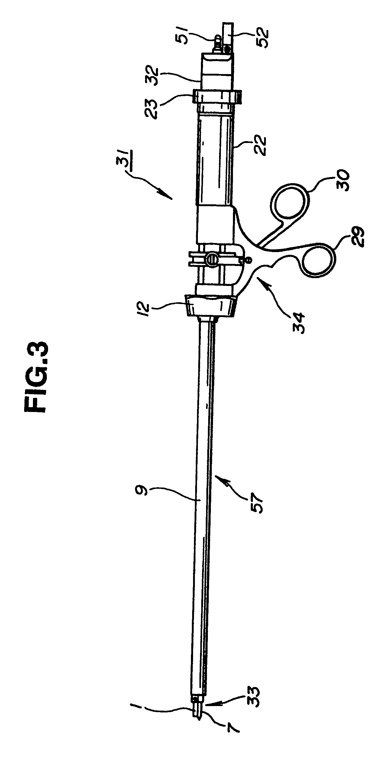
[0185]As shown in FIG. 3, an ultrasound treatment appliance 31 of the first embodiment of the present invention includes an insertion unit 57 having a treatment unit 33, which is used to conduct a treatment, attached to a distal end thereof, and a manipulating means 34 formed at the proximal end of the insertion unit 57 and used to manipulate the treatment unit 33. The insertion unit 57 has an insertion unit armor formed with an elongated sheath 9 so that the insertion unit 57 can be inserted in a living body.

[0186]At the upper proximal end of the manipulating means 34, a sheath 22 whose diameter is larger than that of the sheath 5 is located. A handpiece 32, which supplies ultrasonic vibrations used for incision and coagulation to the treatment unit 33, includes ultrasonic transducers 50 shown in FIG. 9A, and serves as a transducer unit, is formed at the proximal end of the sheath 22.

[0187]As shown in FIG. 4,...

second embodiment

[0251]Referring to FIGS. 12A and 12B, the present invention will be described.

[0252]FIGS. 12A and 12B show a major portion of the second embodiment of the present invention. This embodiment has substantially the same structure as the first embodiment. However, this embodiment aims mainly at incision of a living tissue, and is therefore devoid of the holding member 1. Instead, the distal end of the movable section 3 and the distal member 7 constitute scissors. A living tissue can therefore be incised efficiently and safely.

[0253]The other components are identical to those in the first embodiment. In this embodiment, the distal end of the movable section 3 and the tip of the distal member 7 are pressed against a living tissue to be incised. The movable section 3 is then moved from an open state in a closing direction, whereby ultrasonic vibrations are imposed on the living tissue in contact with the scissors. Thus, the living tissue can be resected.

[0254]In short, this embodiment prov...

third embodiment

[0256]Referring to FIGS. 13A and 13B, the present invention will be described.

[0257]FIGS. 13A and 13B show a major portion of the third embodiment. This embodiment has substantially the same structure as the first embodiment. However, an incision plane 62 is formed on a plane that is opposed to the distal member 7 and interposed between the holding member 1 of the movable section 3 and the distal cover 6.

[0258]After a living tissue is clamped by the holding member 1 and distal member 7, a coagulation plane 61 is used to coagulate the living tissue. The incision plane 62 is formed by narrowing the portion of the movable section 3 proximal to the coagulation plane 61. A thin living tissue clamped by the incision plane 62 and distal member 7 can therefore be incised by them. The other components are identical to those in the first embodiment.

[0259]Owing to the foregoing structure, for example, when incision is conducted concurrently with coagulation, a living tissue is clamped and impo...


PUM


Abstract

An ultrasound treatment system in accordance with the present invention comprises an ultrasonic transducer, a handpiece, a probe, a sheath, a clamping member, an operation unit, an operating member, a suction base, and a perfusion base. The ultrasonic transducer generates ultrasonic vibrations. The handpiece has the ultrasonic transducer incorporated therein and serves as an operation unit. The probe is connected to the ultrasonic transducer, and serves as a vibration transmitting member for transmitting ultrasonic vibrations to a distal member realizing a stationary portion that is a treatment portion for treating a living tissue. The sheath serves as a protecting member for shielding the probe. The clamping member is opposed to the distal member at the distal end of the sheath, and realizes a movable portion that is another treatment portion for clamping a living tissue in cooperation with the distal member. The operation unit is manipulated for clamping a living tissue with the clamping member and distal member or freeing the living tissue therefrom.

Description

[0001]This is a Divisional of U.S. Ser. No. 09 / 353,652 filed Jul. 15, 1999, now U.S. Pat. No. 6,669,690, which is a Continuation-In-Part of U.S. Ser. No. 09 / 345,794 filed Jul. 1, 1999, now abandoned, which is a Divisional of U.S. Ser. No. 08 / 938,523 filed Sep. 26, 1997, now U.S. Pat. No. 6,056,735, which is in turn a Continuation-In-Part application of U.S. Ser. No. 08 / 627,500 filed Apr. 4, 1996, now abandoned.BACKGROUND OF THE INVENTION[0002]1. Field of the Invention[0003]The present invention relates to an ultrasound treatment system for coagulating or resecting the region of a living tissue to be treated.[0004]2. Description of the Related Art[0005]In recent years, it has become a matter of common practice that an endoscope is inserted in a body cavity in order not only to observe an organ in the body cavity but also to conduct various kinds of curative procedures and treatments under the observation through the endoscope.[0006]A means for conducting a curative treatment under en...

Claims


Application Information

Patent Timeline
Patent Type & Authority Patents(United States)
IPC IPC(8): A61B18/18A61B17/28A61B17/32A61B18/14A61M1/00
CPCA61B17/320092A61B18/1482A61B2017/2929A61B2017/320072A61B2017/320084A61B2017/320088A61B2217/005A61B2217/007A61B2017/320073A61B2017/320075A61B2017/320094A61B2017/320095
Inventor OKADA, MITSUMASASUGAI, TOSHIYAHONDA, YOSHITAKAISHIKAWA, MANABUSAKURAI, TOMOHISA
Owner OLYMPUS CORP
Why Eureka
Try Eureka