

Indwelling catheter
- Summary
- Abstract
- Description
- Claims
- Application Information
AI Technical Summary
Benefits of technology
Problems solved by technology
Method used
Image

Examples
first embodiment
[0023]With reference to FIGS. 1 to 4, this invention will be described in detail below.
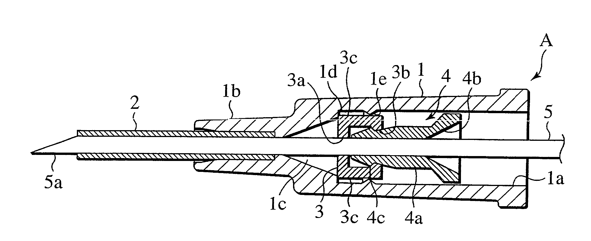
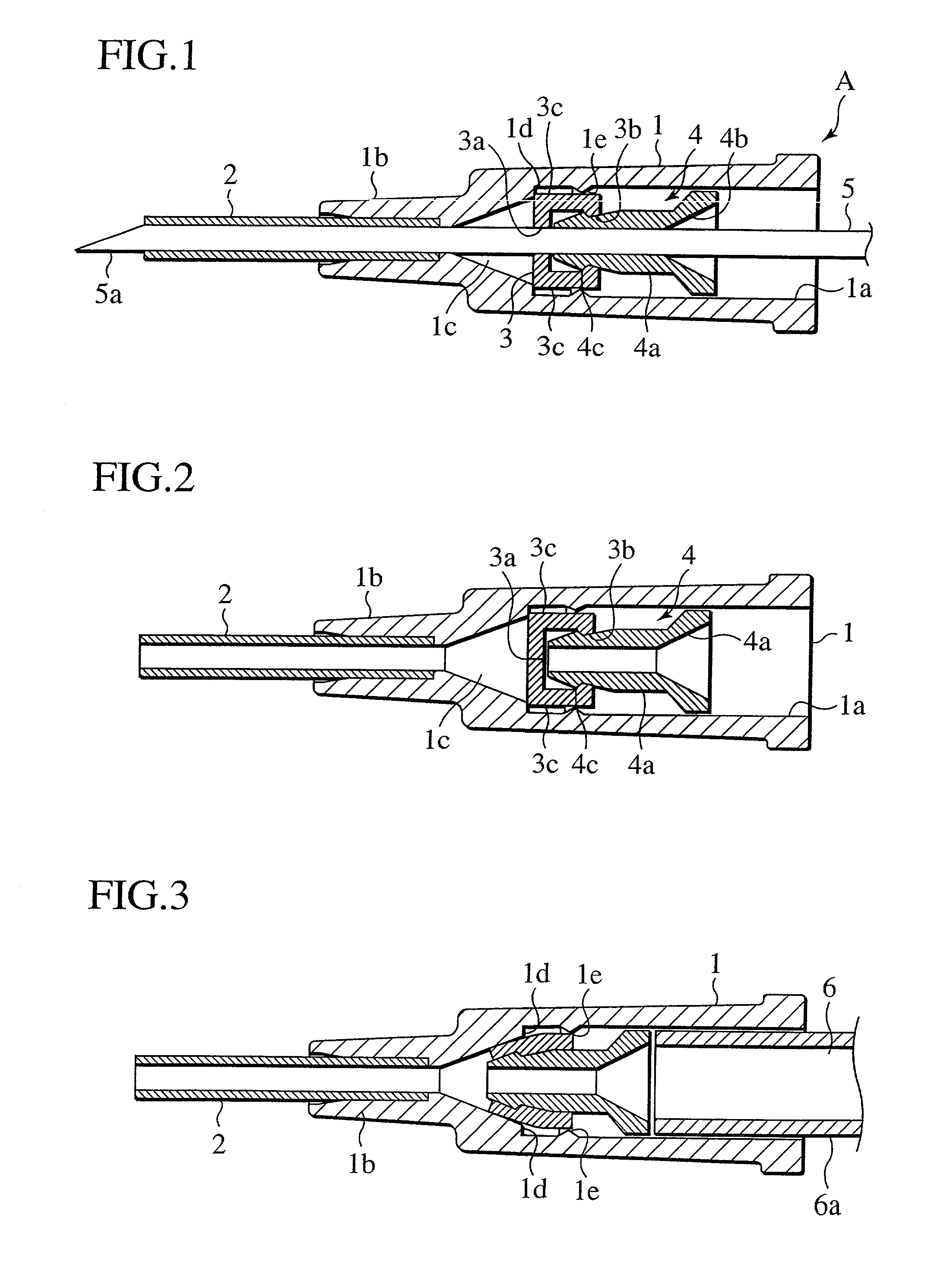
[0024]An indwelling catheter A according to the first embodiment of this invention has, as shown in FIG. 1, a hollow catheter body 1, a catheter tube 2 fitted into a tube holder 1b provided at a distal end of the catheter body 1, an elastic valve 3 fitted inside the catheter body 1, and a hollow plug 4 slidably fitted inside the catheter body 1. The catheter tube 2, the elastic valve 3, and the plug 4 are coaxially aligned in this order.
[0025]The catheter body 1 is made from resin or a like material, and has a tubular shape. An inner surface 1a is tapered toward the distal end, with a gradually reduced diameter.
[0026]The catheter body 1 is preferably of a transparent or semi-transparent material so as to show the interior, enabling checking of movement inside.
[0027]The catheter tube 2 is made from resin such as polyamide, and is press-fitted into the tube holder 1b which communicates at its proxim...
second embodiment
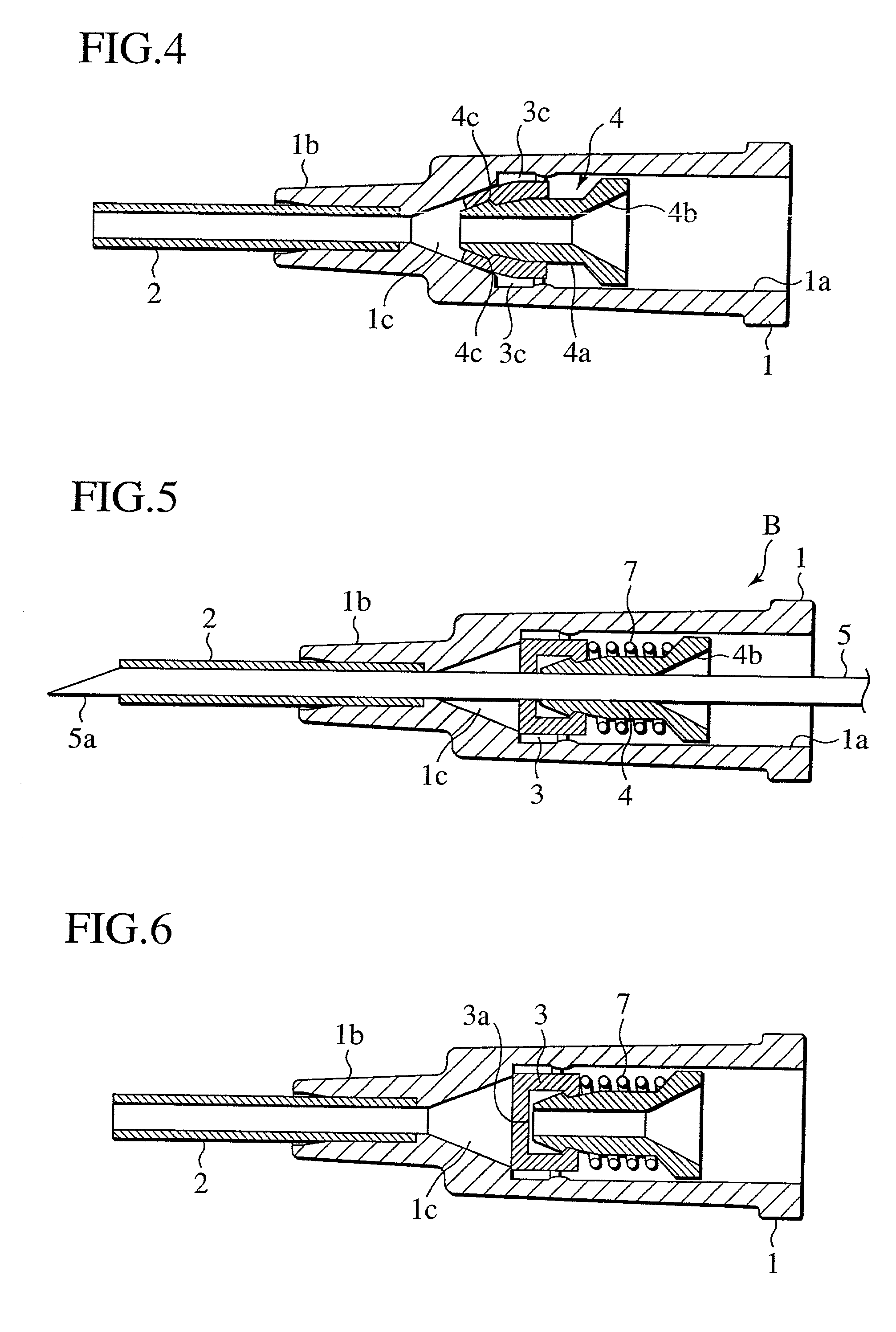
[0040]An indwelling catheter B has the structure identical to that of the indwelling catheter A, and further includes a coil spring 7 biasing a plug 4 in a direction opposite to an elastic valve 3. The coil spring 7 is made from a resilient material and is fitted between the elastic valve 3 and the plug 4.
[0041]A connector 6 is inserted from the rear of a catheter body 1 to press the plug 4 against the biasing force of the coil spring 7. The front end of the plug 4 then penetrates into a valve aperture 3a of the elastic valve 3, providing connection between a catheter tube 2 and a drip tube or the like as shown in FIG. 7.
[0042]Then, the connector 6 is removed, and the plug 4 is returned to its original position by the biasing force of the coil spring 7 as shown in FIG. 8. The elastic valve 3 is thus closed, providing hemostasis. That is, the removal of the connector 6 does not require a special operation for hemostasis, resulting in hemostasis being reliably maintained.
[0043]With r...
third embodiment
[0044]An indwelling catheter C has the structure identical to that of the indwelling catheter B, and has a bellows 8 in place of the coil spring 7 for biasing a plug 4 in a direction opposite to an elastic valve 3. The bellows 8 is made from a resilient material and is fitted between the elastic valve 3 and the plug 4.
[0045]A connector 6 is inserted from the rear of a catheter body 1 to press the plug 4 against the biasing force of the bellows 8. The front end of the plug 4 then penetrates into a valve aperture 3a of the elastic valve 3, providing connection between a catheter tube 2 and a drip tube or the like as shown in FIG. 11.
[0046]Then the connector 6 is removed, and the plug 4 is returned to its original position by the biasing force of the bellows 8 as shown in FIG. 12. The elastic valve 3 is thus closed, providing hemostasis. That is, the removal of the connector 6 does not require a special operation for hemostasis, resulting in hemostasis being securely maintained.
PUM
 Abstract
Description
Claims
Application Information