Freezing device

A refrigeration device and refrigeration cycle technology, applied in refrigerators, refrigeration components, refrigeration and liquefaction, etc., can solve the problem of not considering the individual control of operating capacity, and achieve the effect of improving the rising characteristics and improving the COP

Inactive Publication Date: 2008-12-03
DAIKIN IND LTD
View PDF1 Cites 11 Cited by
  • Summary
  • Abstract
  • Description
  • Claims
  • Application Information

AI Technical Summary

Problems solved by technology

[0007] However, in the refrigerating device of the above-mentioned patent document 1, the problem of how to individually control the operating capacity of each compression mechanism performing two-stage compression during the operation of the two-stage compression refrigeration cycle is not considered at all.
Therefore, in the conventional refrigerating apparatus, there is a problem that it is difficult to say that the compression mechanism is properly controlled according to the operating conditions.

Method used


Image

  • Freezing device
  • Freezing device
  • Freezing device

Examples


Embodiment approach 1

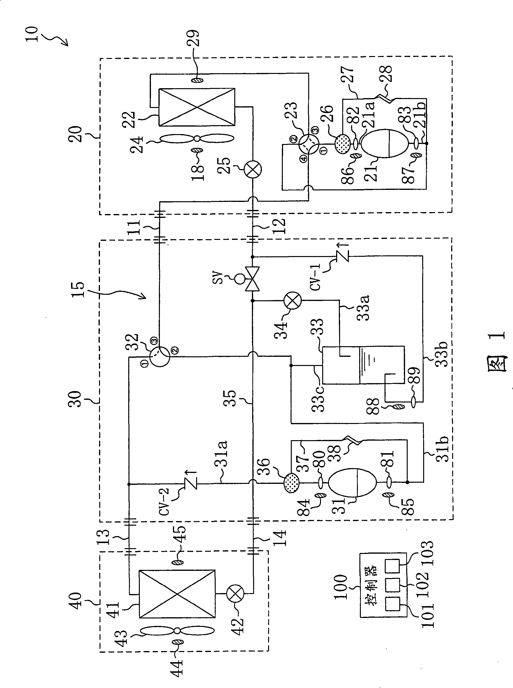
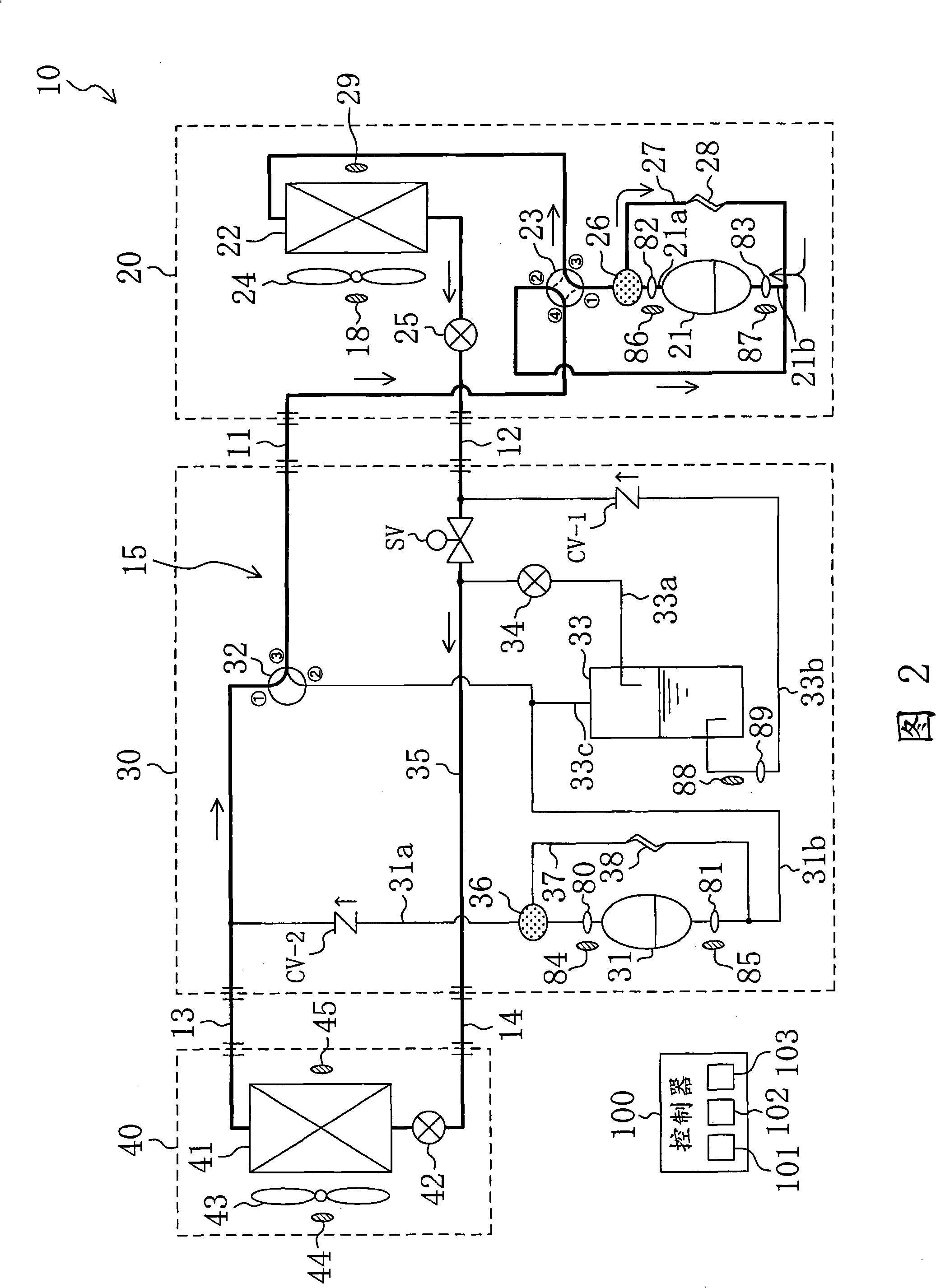
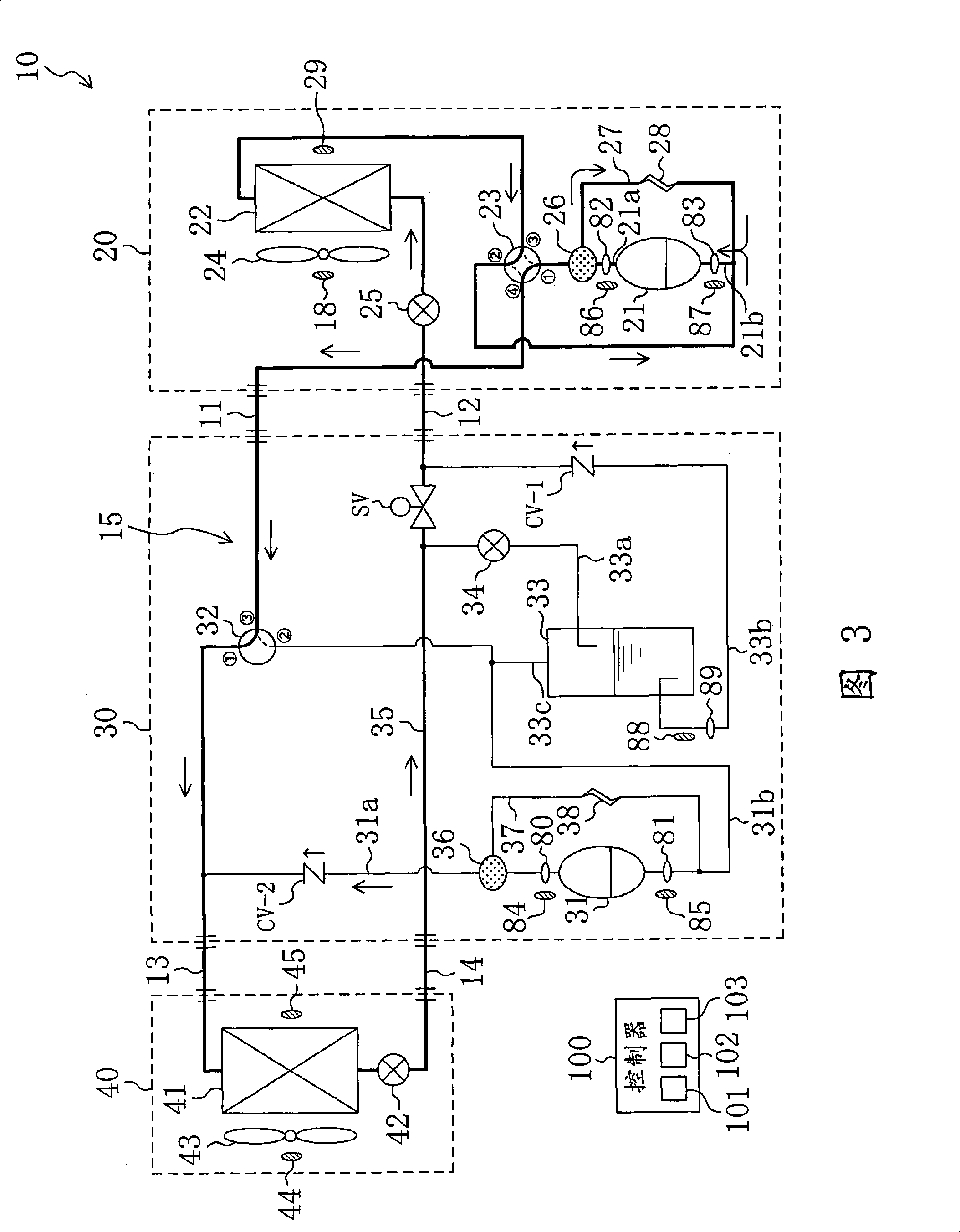
[0053] As shown in FIG. 1 , an apparatus according to Embodiment 1 of the present invention is a heat pump air conditioner 10 capable of cooling operation and heating operation. The air conditioner 10 includes an outdoor unit 20 installed outdoors, an optional unit 30 constituting an extension unit, an indoor unit 40 installed indoors, and a controller 100 for controlling the operation of the air conditioner 10 . The outdoor unit 20 is connected to the selection unit 30 through the first connecting pipe 11 and the second connecting pipe 12 . In addition, the indoor unit 40 is connected to the selection unit 30 through the third connecting pipe 13 and the fourth connecting pipe 14 . As a result, the refrigerant circuit 15 is configured in the air conditioner 10 , and the refrigerant circulates in the refrigerant circuit 15 to perform a vapor compression refrigeration cycle.

[0054] In addition, the selection unit 30 constitutes the booster unit of the original separate type a...

Embodiment approach 2

[0123] As shown in FIG. 6 , the device according to Embodiment 2 of the present invention is a refrigeration device 120 that cools a cooling chamber. The refrigeration unit 120 includes an outdoor unit 20 installed outdoors, an optional unit 30 constituting an extension unit, an indoor unit 40 installed in the cooling room, and a controller 100 for controlling the operation of the refrigeration unit 120 . The outdoor unit 20 is connected to the selection unit 30 through the first connecting pipe 11 and the second connecting pipe 12 . In addition, the indoor unit 40 is connected to the selection unit 30 through the third connecting pipe 13 and the fourth connecting pipe 14 . Thus, the refrigerant circuit 15 is configured in the refrigeration device 120, and the refrigerant circulates in the refrigerant circuit 15 to perform a vapor compression refrigeration cycle.

[0124] In addition, the selection unit 30 constitutes an augmentation unit of the original split refrigeration u...


PUM


Abstract

The present invention discloses a freezing device (10) including: a coolant circuit (15) having a low-stage compressor (21) and a high-stage compressor (31) whose capacity can be varied for performing two-stage compression freezing cycle; and a controller (100) for controlling operation of the freezing device (10). The controller (100) includes a first control unit (101) and a second control unit (102). The first control unit (101) controls operation capacity of the low-stage compressor (21) in accordance with the load of the freezing capability. The second control unit (102) controls operation capacity of the high-stage compressor (31) so that a first pressure ratio between the intake pressure and discharge pressure of the low-stage compressor (21) and a second pressure ratio between the intake pressure and discharge pressure of the high-stage compressor (31) are in the relationship of 1:1.

Description

technical field [0001] The present invention relates to a refrigerating apparatus including a refrigerant circuit having two compression mechanisms, and more particularly to the control of the operating capacity of a compression mechanism in which a two-stage compression refrigeration cycle is performed. Background technique [0002] Conventionally, a refrigerating apparatus including two compression mechanisms and subjecting a refrigerant to a two-stage compression refrigeration cycle has been known (for example, Patent Document 1). [0003] The refrigerating apparatus described in Patent Document 1 is an air-conditioning apparatus including an outdoor unit, an indoor unit, and a power up unit that is mainly used to increase capacity by performing two-stage compression operation during heating operation. The outdoor unit is provided with an outdoor expansion valve, an outdoor heat exchanger, and a low-stage compressor as a main compression mechanism, and the indoor unit is ...

Claims


Application Information

Patent Timeline
Patent Type & Authority Applications(China)
IPC IPC(8): F25B1/10F25B1/00
CPCF25B2700/2106F25B2700/2109F25B2313/006F25B2313/0315F25B2700/1931F25B13/00F25B49/025F25B2400/23Y02B30/741F25B2313/02731F25B2313/0314F25B2500/26F25B2700/21152F25B2700/1933F25B1/10F25B2700/2104F25B2600/021F25B2313/02741Y02B30/70F25B1/00
Inventor 藤本修二吉见敦史山口贵弘
Owner DAIKIN IND LTD
Why Eureka
Try Eureka