

Wireless network system and relay node
A wireless network system and wireless node technology, applied in the field of wireless network systems, can solve the problems of deterioration of data communication reliability, increase of installation cost of relay nodes, etc.
- Summary
- Abstract
- Description
- Claims
- Application Information
AI Technical Summary
Problems solved by technology
Method used
Image

Examples
application example 1
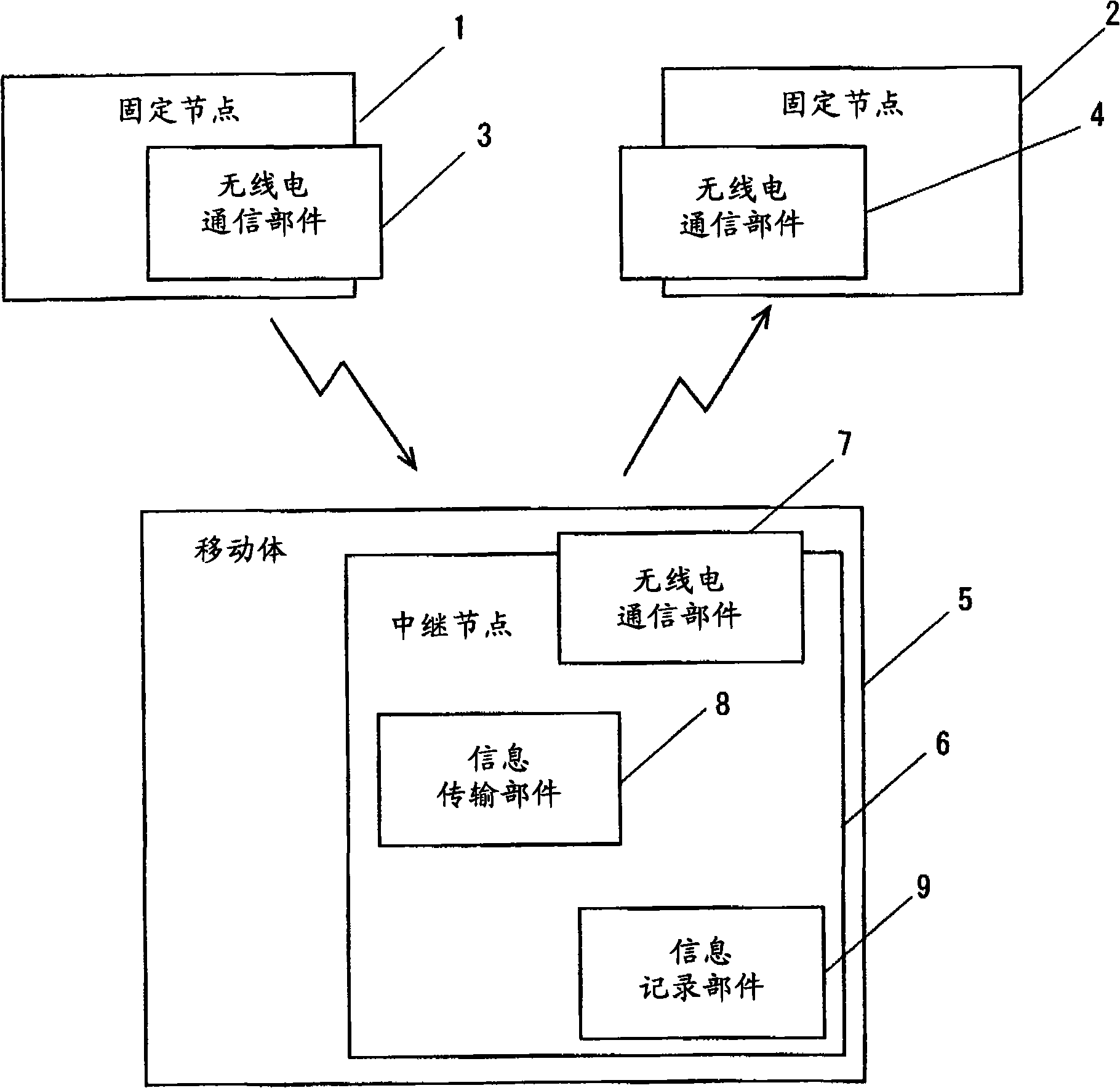
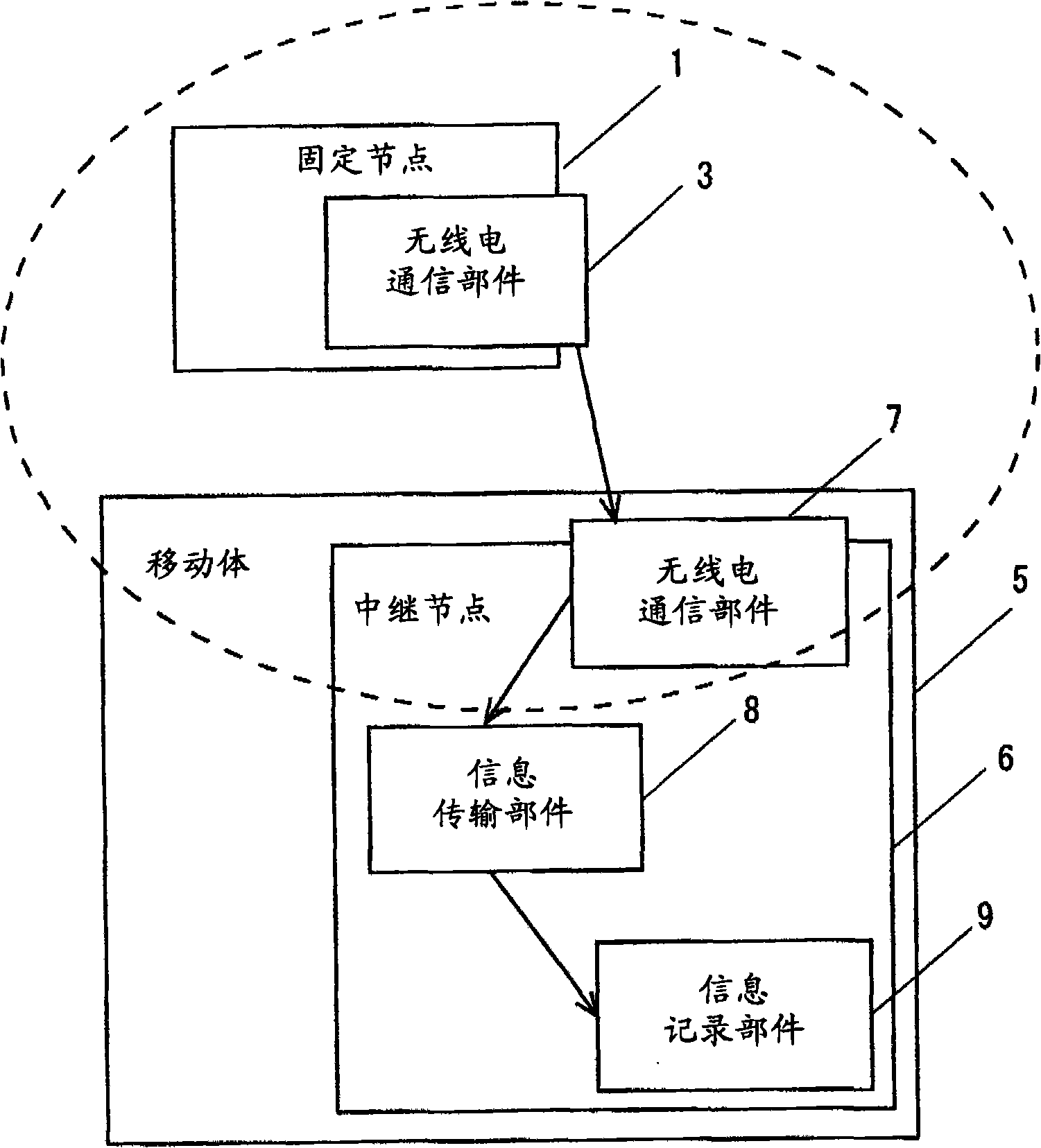
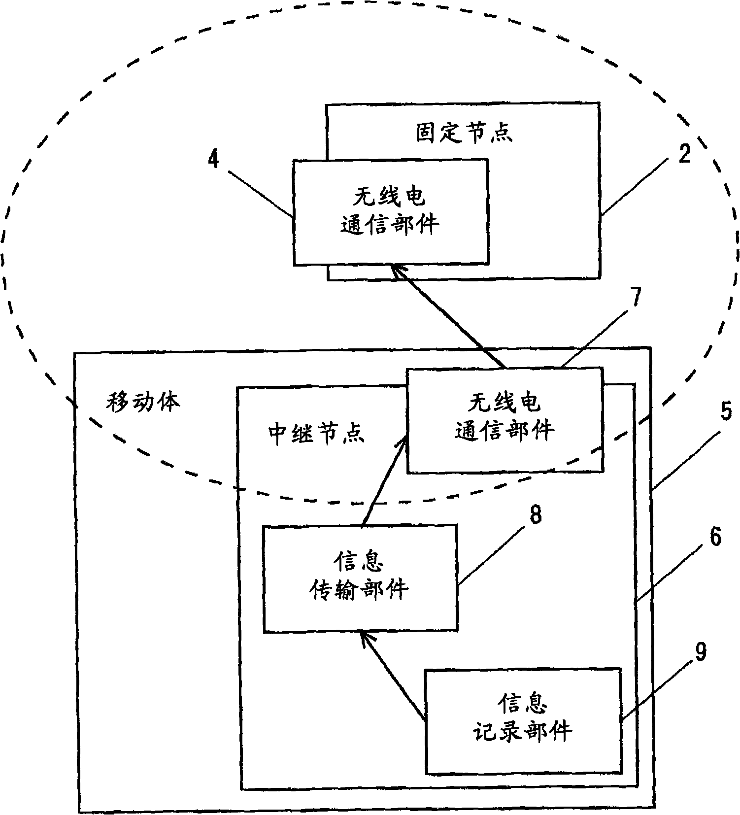
[0035] figure 1 is a diagram explaining the basic structure of a wireless network system according to Application Example 1 of the present invention. figure 1 A case is shown in which two fixed nodes are provided.
[0036] The fixed node 1 comprises a radio communication part 3, wherein the radio communication part 3 comprises an antenna module. Similarly, the fixed node 2 comprises a radio communication part 4, wherein the radio communication part 4 comprises an antenna module. The communicable ranges of the fixed nodes 1 and 2 do not overlap with each other, making it impossible to establish direct wireless communication between them. The mobile body 5 moving between the fixed node 1 and the fixed node 2 includes a relay node 6 mounted thereon. The relay node 6 includes a radio communication section 7 , an information transmission section 8 , and an information recording section 9 . It should be noted that both the fixed node 1 and the fixed node 2 comprise equipment f...
application example 2
[0044] Figure 4A and Figure 4B is a diagram explaining a wireless network system according to Application Example 2 of the present invention. Figure 4A shows the received message status, while the Figure 4B Shows the transmit information status.
[0045] The car 10 , as an example of a mobile body, includes the relay node 61 mounted thereon, and travels along the road 100 at a speed of 60 km / h. When the car 10 enters the communicable range of the fixed node 11 mounted on the pole 20 , communication between the relay node 61 and the fixed node 11 starts. Figure 4A The communication range of the fixed node 11 with the pole 20 as the center and a radius of 1 km is indicated by a dotted line in . The communication between the fixed node 11 and the relay node 61 is completed before the car 10 leaves the communicable range of the fixed node 11 . In this case, the relay node 61 receives destination information indicating that the destination is the fixed node 21 from the fi...
application example 3
[0048] Figure 5A and Figure 5B is a diagram explaining a wireless network system according to Application Example 3 of the present invention. Figure 5A shows the received message status, while the Figure 5B Shows the transmit information status.
[0049] The electric train 40 , as an example of a mobile body, includes the relay node 62 mounted thereon, and travels along the track 200 at a speed of 100 km / h. When the electric train 40 enters the communicable range of the fixed node 12 installed on the pole 80 , the communication between the relay node 62 and the fixed node 12 starts. Figure 5A The communicable range of the fixed node 12 centered on the rod 80 with a radius of 1 km is indicated by a dotted line in . The communication between the fixed node 12 and the relay node 62 is completed before the electric train 40 leaves the communicable range of the fixed node 12 . At this time, the relay node 62 receives destination information indicating that the destination...
PUM
 Abstract
Description
Claims
Application Information