
Pre-bending device
A technology of pre-bending and driving device, applied in the field of pre-bending device, can solve problems such as straightening and inability to meet production requirements
- Summary
- Abstract
- Description
- Claims
- Application Information
AI Technical Summary
Problems solved by technology
Method used
Image

Examples
Embodiment Construction
[0012] The present invention will be further described below in conjunction with the accompanying drawings.
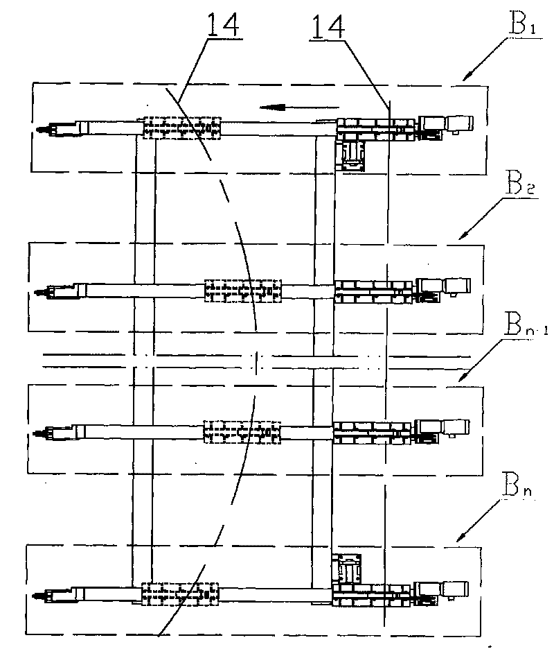
[0013] figure 1 As shown, the described pre-bending device consists of several pre-bending trolleys B arranged side by side 1 ~B n Composition, the number of pre-bending trolleys B can be determined according to the length of the produced special-shaped steel to ensure the amount of pre-bending in the opposite direction of the special-shaped steel.
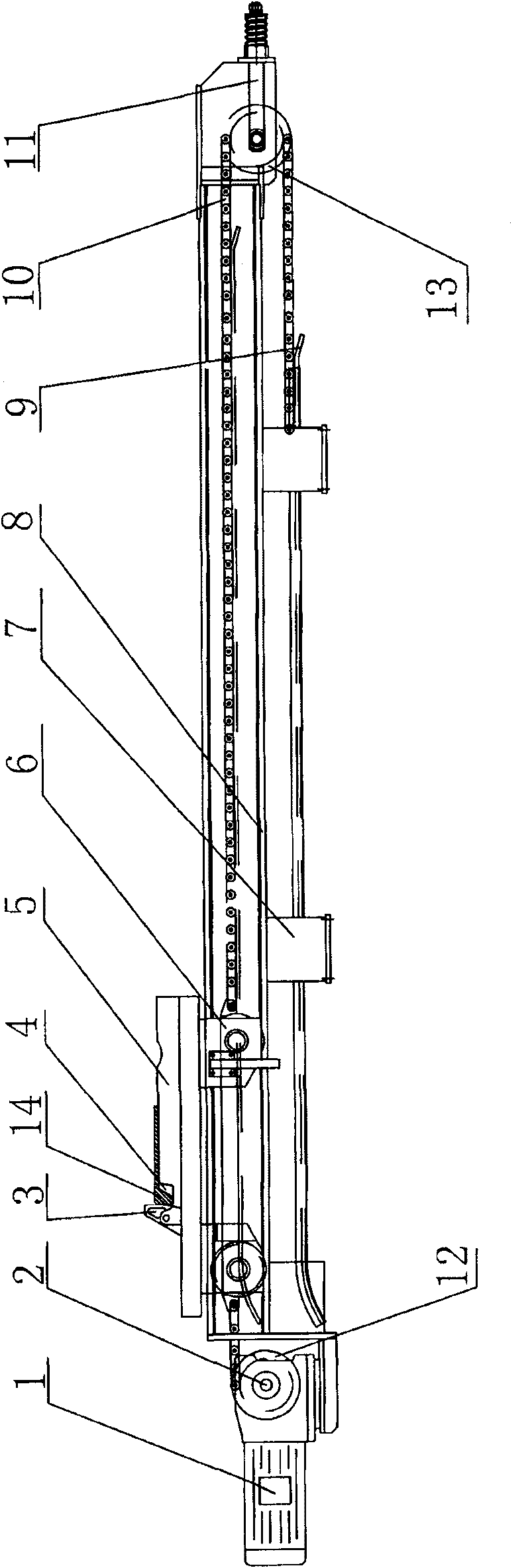
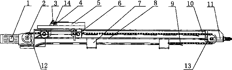
[0014] figure 2 As shown, the structure of each pre-bending trolley B is as follows: a driving device 1 and a trolley guide rail 8 are arranged on the bracket 7 of the pre-bending trolley B, a drive sprocket 12 is arranged on the output shaft of the driving device 1, and a driving sprocket 12 is arranged on the trolley guide rail 8. A mobile trolley 6 is provided, and one end of the chain 10 is fixed on the mobile trolley 6, and the other end is fixed on the side of the mobile trolley 6 after bypassing the driven sproc...
PUM
 Abstract
Description
Claims
Application Information