This helps you quickly interpret patents by identifying the three key elements:
Problems solved by technology
Method used
Benefits of technology
Problems solved by technology
As a result, a detection error may cause the entire system to malfunction
Method used
Image
Click on the blue label to locate the original text in one second.
Reading with bidirectional positioning of images and text.
Examples
Embodiment 1
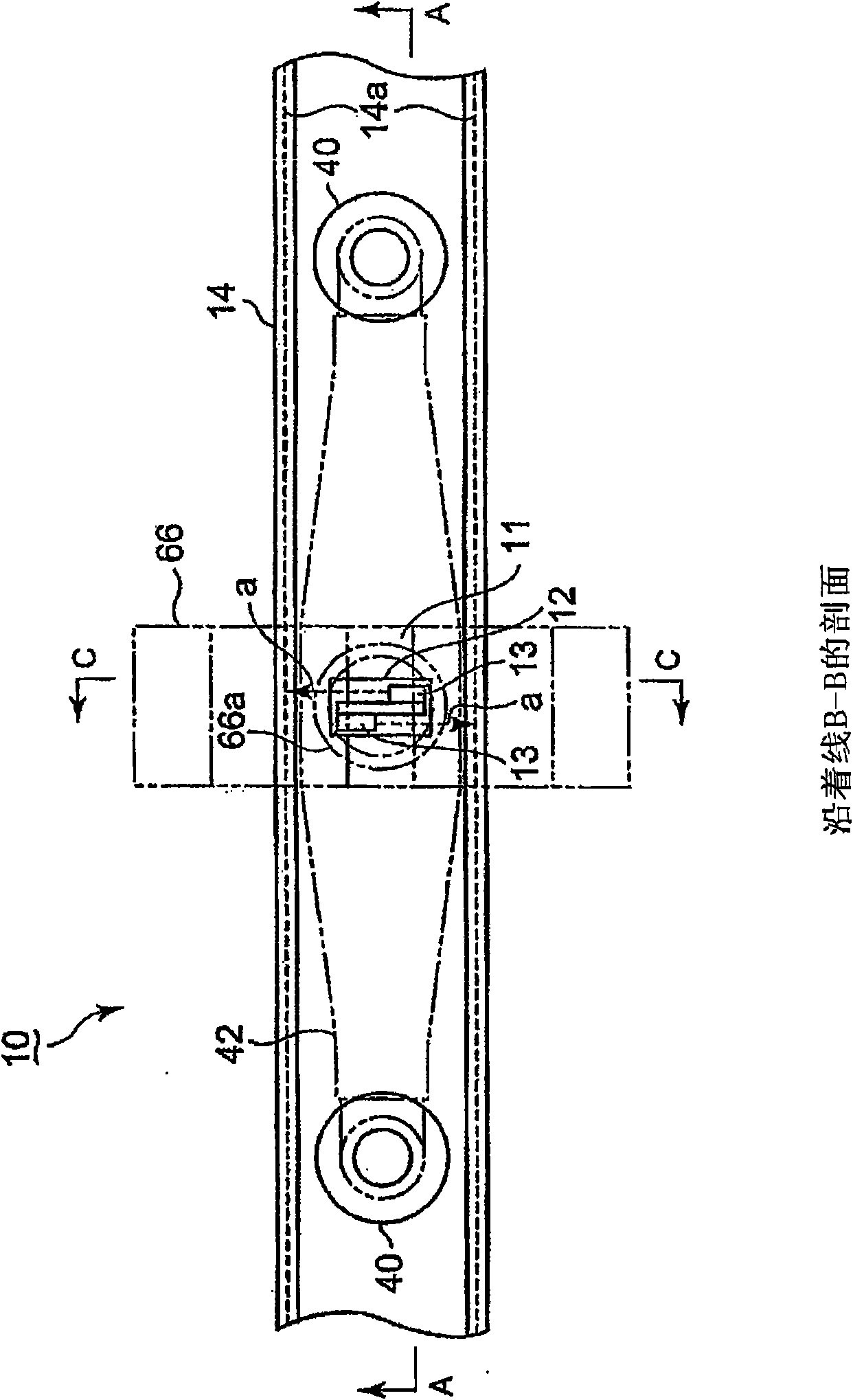
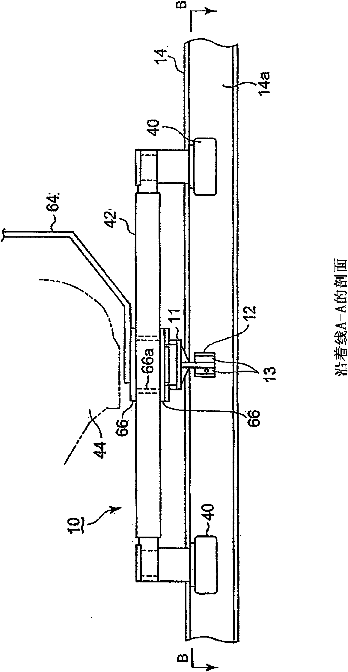
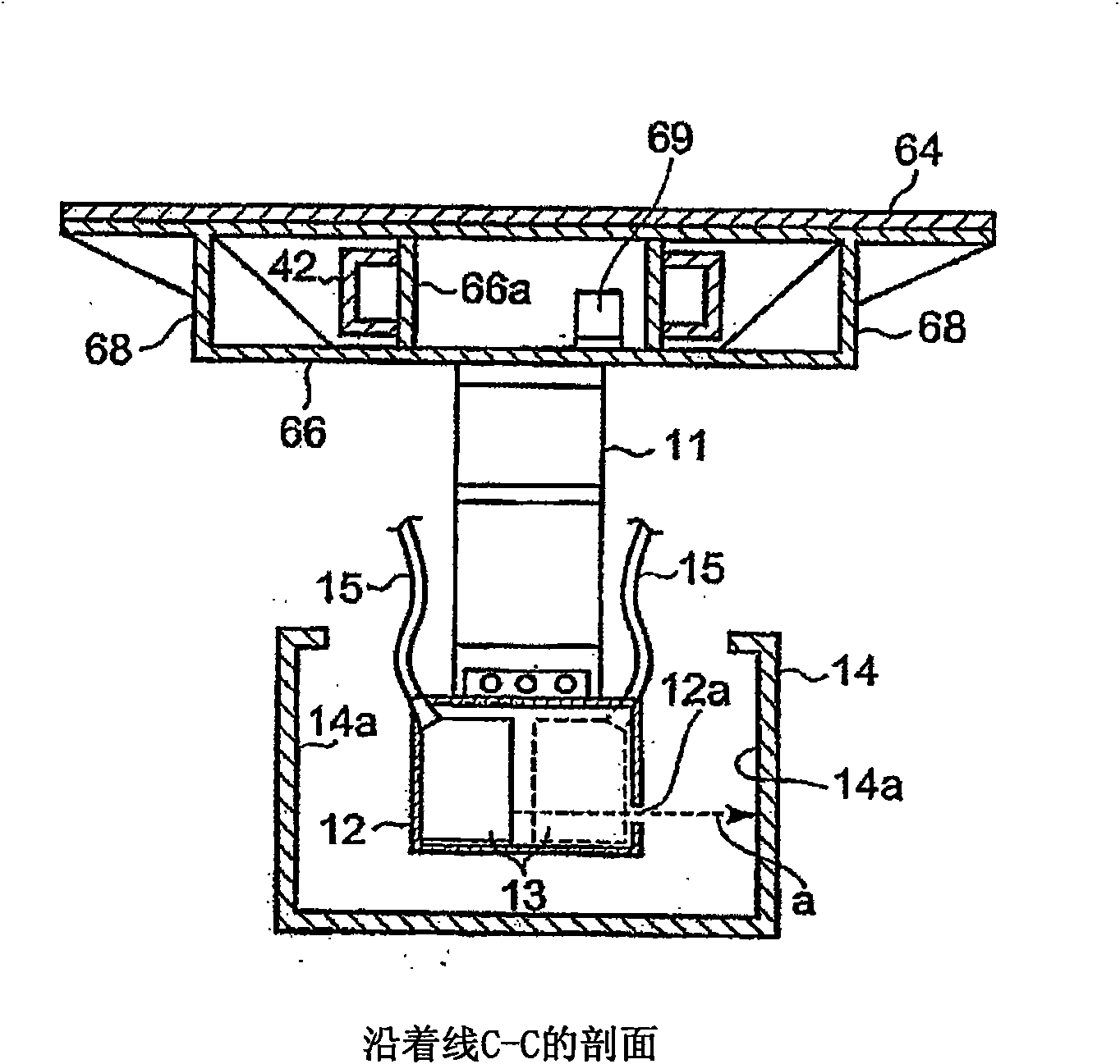
[0089] The following will refer to Figure 1 to Figure 3 Describe the first embodiment of the rail-type transportation system in the present invention, wherein, figure 1 is a plan sectional view showing the fail-safe mechanism in this embodiment (along figure 2 the line B-B), figure 2 is the elevation section view (along figure 1 line A-A), while image 3 is a side sectional view (along figure 1 line C-C).
[0090] The configurations of the automatic steering mechanism and the fail-safe mechanism 10 in this embodiment are the same as those described in the above-mentioned Patent Document 1, and therefore, description thereof is omitted. In this embodiment, a displacement meter is provided for detecting the deviation value of the pivot center of the guard arm relative to the guard rail (pivot of the guard arm 42) in combination with the automatic steering mechanism and the fail-safe mechanism disclosed in Patent Document 1. The deviation value of the center in the wi...
Embodiment 2
[0103] Next refer to Image 6 and Figure 7 A second embodiment of the present invention is described in which, Image 6 is a plan view (along Figure 7 the line G-G), while Figure 7 is the elevation section view (along Image 6 line F-F). In this embodiment, compared with the first embodiment, a pair of laser displacement gauges 13, 13 is located at the center position of the axle shaft, and is arranged so that the laser beam a from the pair of laser displacement gauges is directed at an oblique angle. The side walls 14 a of the guard rail 14 are irradiated obliquely. In addition, a sensor cover 12 surrounding the laser displacement gauges 13, 13 is provided.
[0104] With the above embodiment, the irradiation distance of the laser beam a from the laser displacement gauges 13, 13 to the left and right side walls 14a can be sufficiently ensured. Thereby, the irradiation distance of the laser beam a is sufficient for accurate measurement, so that it is possible to impro...
Embodiment 3
[0106] Next will refer to Figure 8 and Figure 9 A third embodiment of the present invention is described, wherein, Figure 8 is a plan view (along Figure 9 the line I-I), and Figure 9 is the elevation section view (along Figure 8 line H-H). In this embodiment, a pair of laser displacement gauges 13 , 13 arranged at the pivot center of the guard arm via a bracket 11 is arranged to be oriented in the direction of travel b of the guard wheel 40 . In addition, mirror holders 16 are placed between the displacement gauges described above. The bracket 11 is fixed at its central portion with upper and lower fixing plates 21 between which the mirror frame 16 is inserted, and the mirror frame is thus held between the fixing plates 21 to extend in the horizontal direction.
[0107] A mirror 17 is fixed to the mirror frame 16 , and the mirror frame 16 is attached to the fixing plate 21 at its upper and lower surfaces with bolts for fixing the mirror frame 16 to the fixing plate...
PUM
Abstract
A track-based traffic system having an automatic steering mechanism and a fail-safe mechanism, in which a detection mechanism highly accurately detects the amount of displacement of a vehicle in the lateral direction of a track and has high reliability. The track-based traffic system has the steering mechanism for automatically steering front wheels and rear wheels of the vehicle by an actuator, and also has the fail-safe mechanism (10) including a protection track defined on the road surface of the track and also including protection wheels (40) provided at the lower part of the vehicle and moving within the protection track without contact. The track-based traffic system further has a pair of non-contact displacement meters (13) attached to a support bracket suspended from the lower part of a vehicle body, placed within the protection track (14), and installed so that detection waves (a) are radiated to left and right side-walls (14a), respectively, of the protection track. The pair of non-contact displacement meters measures the distances from the displacement meters to the left and right side-walls of the protection track.
Description
technical field [0001] The present invention relates to a track type transportation system for vehicles traveling on a predetermined track, and more particularly to a track type transportation system in which the front wheels and rear wheels of the vehicles are made of The steering is automatically steered by the actuator, and the system includes a fail-safe mechanism to prevent the vehicle from leaving the track in the event of a failure of the automatic steering mechanism. Background technique [0002] The present applicant has proposed a rail-type transportation system for vehicles, which includes a steering mechanism for automatically steering the front and rear wheels of the vehicle through an actuator, so that the vehicle Travels on a predetermined track, and the fail-safe mechanism is used to prevent the vehicle from leaving the track even when the automatic steering mechanism fails (refer to a patent document: Japanese Patent Laid-Open No. 2006-306334). The rail-typ...
Claims
Application Information
Patent Timeline
Application Date:The date an application was filed.
Publication Date:The date a patent or application was officially published.
First Publication Date:The earliest publication date of a patent with the same application number.
Issue Date:Publication date of the patent grant document.
PCT Entry Date:The Entry date of PCT National Phase.
Estimated Expiry Date:The statutory expiry date of a patent right according to the Patent Law, and it is the longest term of protection that the patent right can achieve without the termination of the patent right due to other reasons(Term extension factor has been taken into account ).
Invalid Date:Actual expiry date is based on effective date or publication date of legal transaction data of invalid patent.

