Shielded power coupling device

A power coupling and shielding technology, applied to circuits, inductors, electrical components, etc., can solve problems such as unsatisfactory radio frequency (RF) radiation, increased leakage inductance, and reduced power transmission efficiency

Active Publication Date: 2015-02-25
ANLOGIC CORP (US)
View PDF6 Cites 0 Cited by
  • Summary
  • Abstract
  • Description
  • Claims
  • Application Information

AI Technical Summary

Problems solved by technology

For example, lack of adequate shielding can lead to undesirable RF (radio frequency) emissions, increased leakage inductance, and / or reduced power transfer efficiency, etc.

Method used


Image

  • Shielded power coupling device
  • Shielded power coupling device
  • Shielded power coupling device

Examples


Embodiment Construction

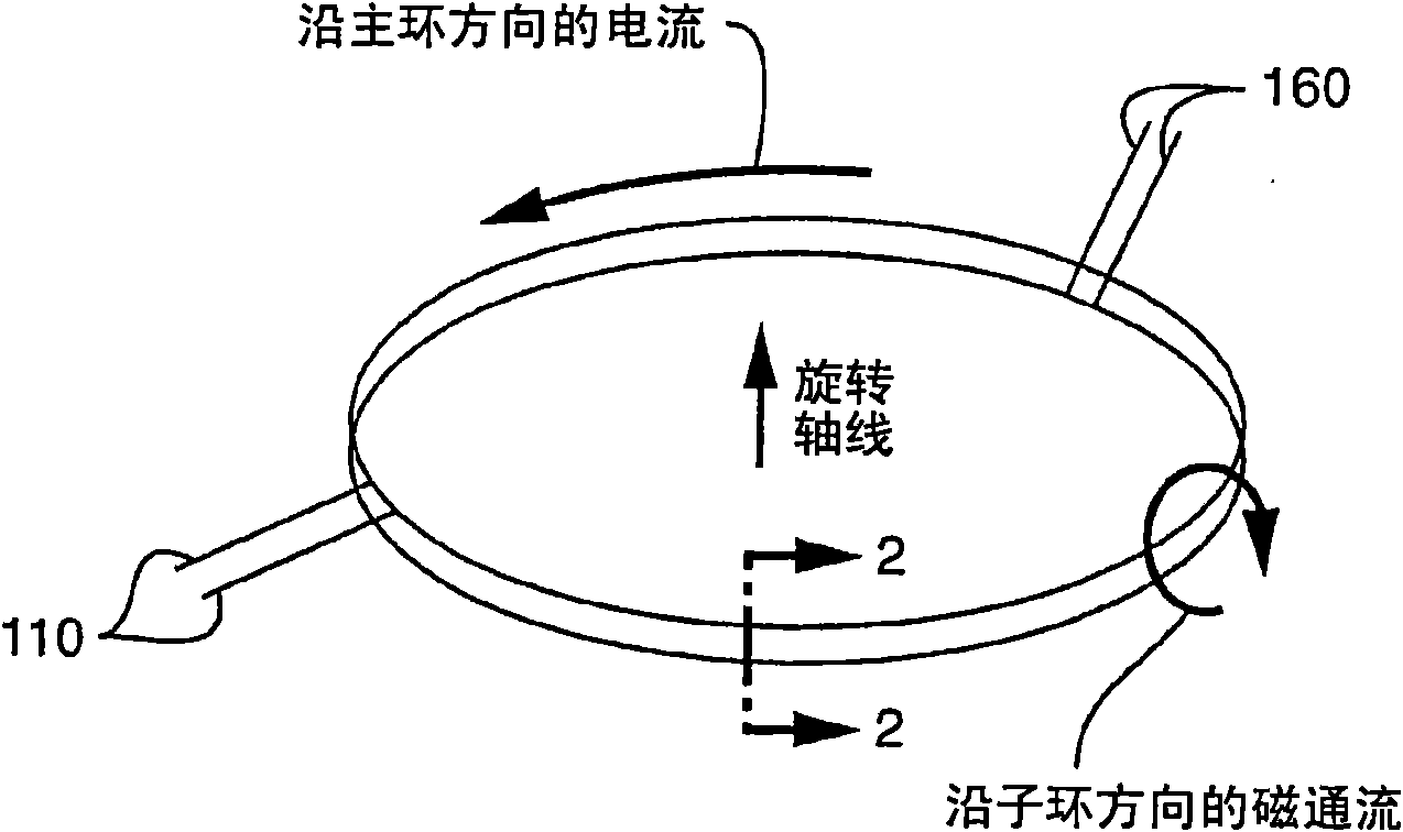
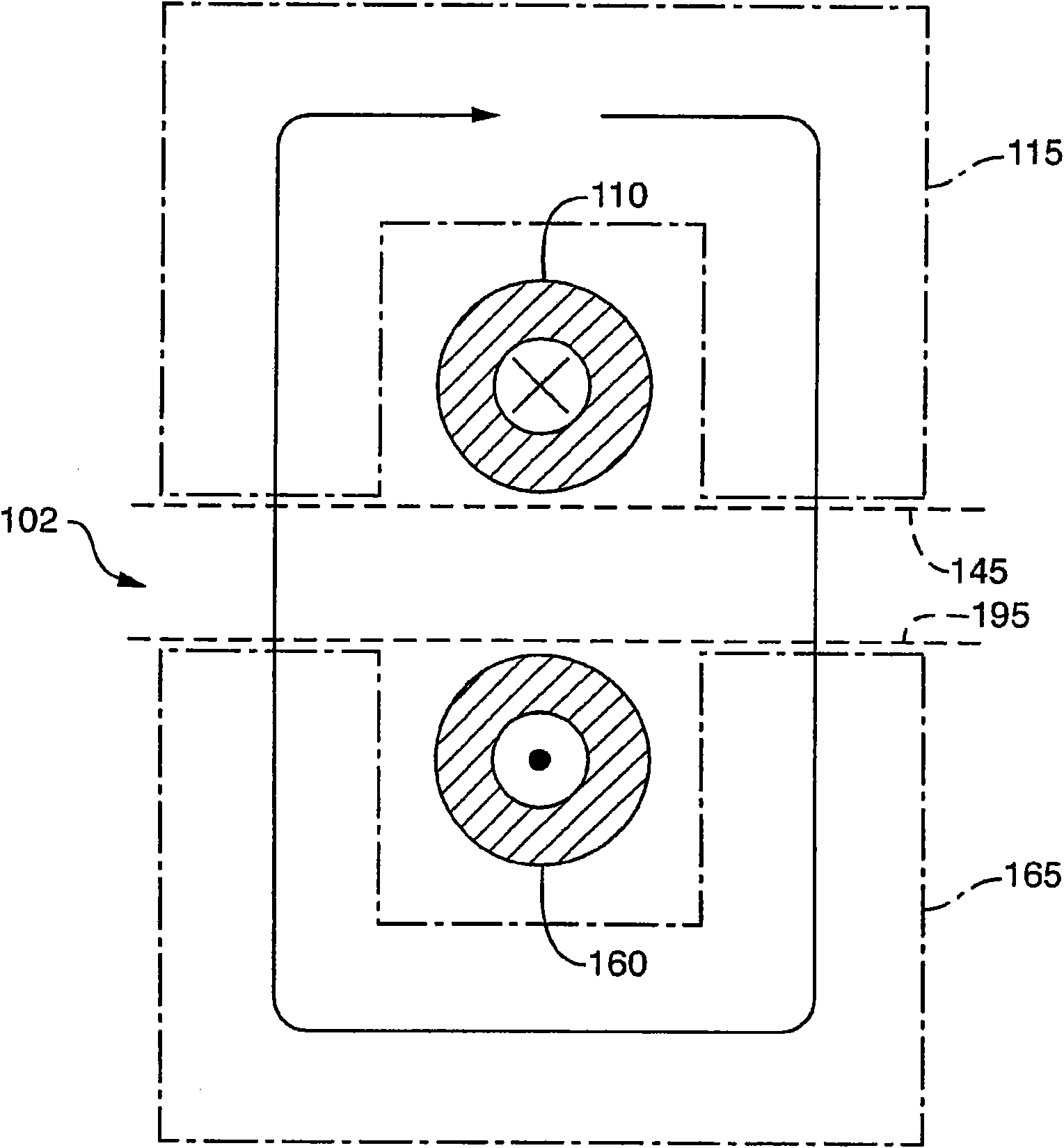
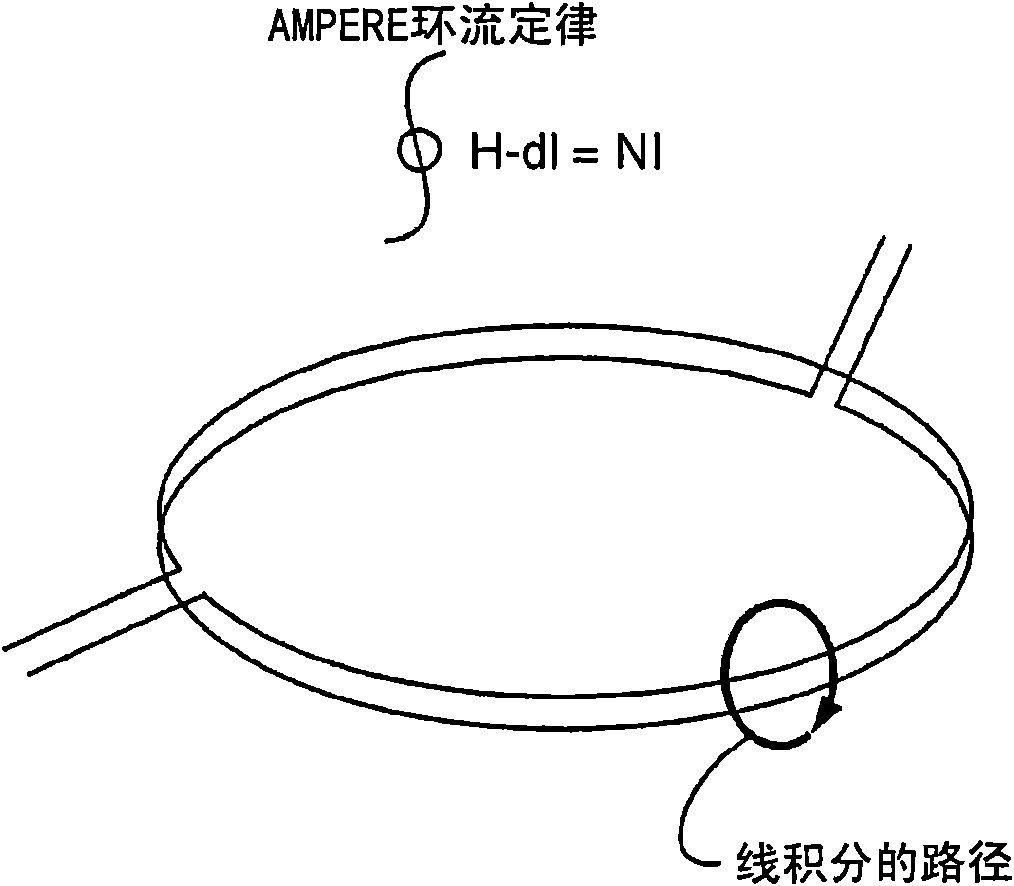
[0041] The present invention relates to a shielded power coupling device, and more particularly to a shielded power coupling device capable of reducing radio frequency radiation and / or other electromagnetic interference when inductively transmitting power in a device environment, Reduce leakage inductance and / or improve efficiency, the equipment environment can be, for example, a computer tomography (CT) scanner and the like that can be used for medical purposes, security purposes or similar purposes, or can be other needs in the An equipment environment in which electrical power is transmitted between bodies engaged in relative rotation.

[0042] The terms "electromagnetic interference", "radio frequency (RF) radiation" and similar terms are used herein in their broadest sense when interference from surrounding equipment affects the operation of a power coupling device according to the present invention The meaning is understood to include the interference from surrounding eq...


PUM


Abstract

#CMT# # / CMT# An inductive coupling field receiving element converts an inductive coupling field to electric power. An inductive coupling efficiency increasing element increases coupling between an inductive field generating element and the inductive field receiving unit. A shielding on the periphery of the inductive coupling efficiency increasing element is capable of eliminating leakage of electromagnetic radiation when it is operated at power levels exceeding 2.5 kW. #CMT# : # / CMT# Independent claims are included for the following: (1) method for transferring electric power between stationary subsystem and rotatable subsystem; (2) flux-aligning core set for use with windings and shields; (3) passage-containing core segment; and (4) system including shielded inductive power coupling device. #CMT#USE : # / CMT# For e.g. computed tomography (CT) scanner for medical and security applications. #CMT#ADVANTAGE : # / CMT# The device reduces radio frequency and other electromagnetic interference, leakage inductance and improves efficiency during inductive transfer of electric power. #CMT#DESCRIPTION OF DRAWINGS : # / CMT# The figure shows a perspective view of the windings centered on an axis of rotation and lying in mutually parallel planes. 110,116 : Windings.

Description

[0001] Research sponsored by the U.S. Federal Government: [0002] Not applicable [0003] Name of party to collaborative research agreement: [0004] Not applicable [0005] Citations of material on the CD are incorporated by: [0006] Not applicable [0007] Cross References to Related Applications [0008] This application is a continuation of application under 35 USC 120 claiming patent application number 10 / 787270 filed February 26, 2004 entitled "Power Coupling Apparatus" and pending Priority to the commonly-owned U.S. patent application 10 / 787270, which also claims application number 60 / 450038 under 119(e) of title 35 of the United States Code, entitled "Contactless Power Coupling Apparatus", priority of the expired U.S. provisional application filed on February 26, 2003. Additionally, the contents of US Patent Application 10 / 787,270 and US Provisional Application 60 / 450,038 are incorporated herein by reference in their entirety. technical field [0009] The pres...

Claims


Application Information

Patent Timeline
Patent Type & Authority Patents(China)
IPC IPC(8): H01F21/06
CPCA61B6/56H01F38/18H01F27/367H01F27/36H01F27/363
Inventor J·M·多布斯
Owner ANLOGIC CORP (US)
Why Eureka
Try Eureka