Al technical title is built by PatSnap Al team. It summarizes the technical point description of the patent document.
An oil pump and hydraulic technology, applied in the field of hydraulic driven oil production equipment, can solve the problems of disconnection of sucker rods, oil pipe leakage detection, shortening the pump cycle, etc. low cost effect
Active Publication Date: 2010-07-21
克拉玛依九工环保技术有限公司
View PDF0 Cites 4 Cited by
Summary
Abstract
Description
Claims
Application Information
AI Technical Summary
This helps you quickly interpret patents by identifying the three key elements:
Problems solved by technology
Method used
Benefits of technology
Problems solved by technology
Traditional rod oil production equipment also has problems. The sucker rod breaks off due to eccentric wear and the tubing leaks due to eccentric wear, which shortens the pump inspection cycle; existing rodless oil production equipment, such as electric submersible pumps, hydraulic piston pumps, jet Pumps, etc. have their own defects that are difficult to overcome, resulting in great limitations in the use of these types of pumps
At present, in the world, there is no oil production equipment with a wide range of lowering depths, a wide range of use, safety and reliability, long service life, and low cost of use to play a leading role in the production of horizontal wells, directional wells, and wells with frequent rod breakage
Method used
Image
Click on the blue label to locate the original text in one second.
Reading with bidirectional positioning of images and text.
Examples
Embodiment Construction
[0026] The following examples are used to illustrate the present invention, but not to limit the scope of the present invention.
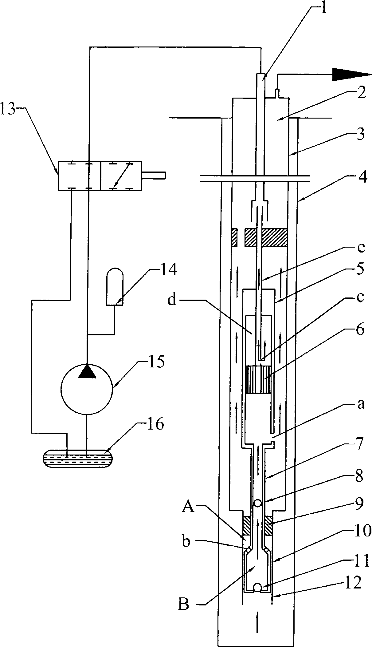
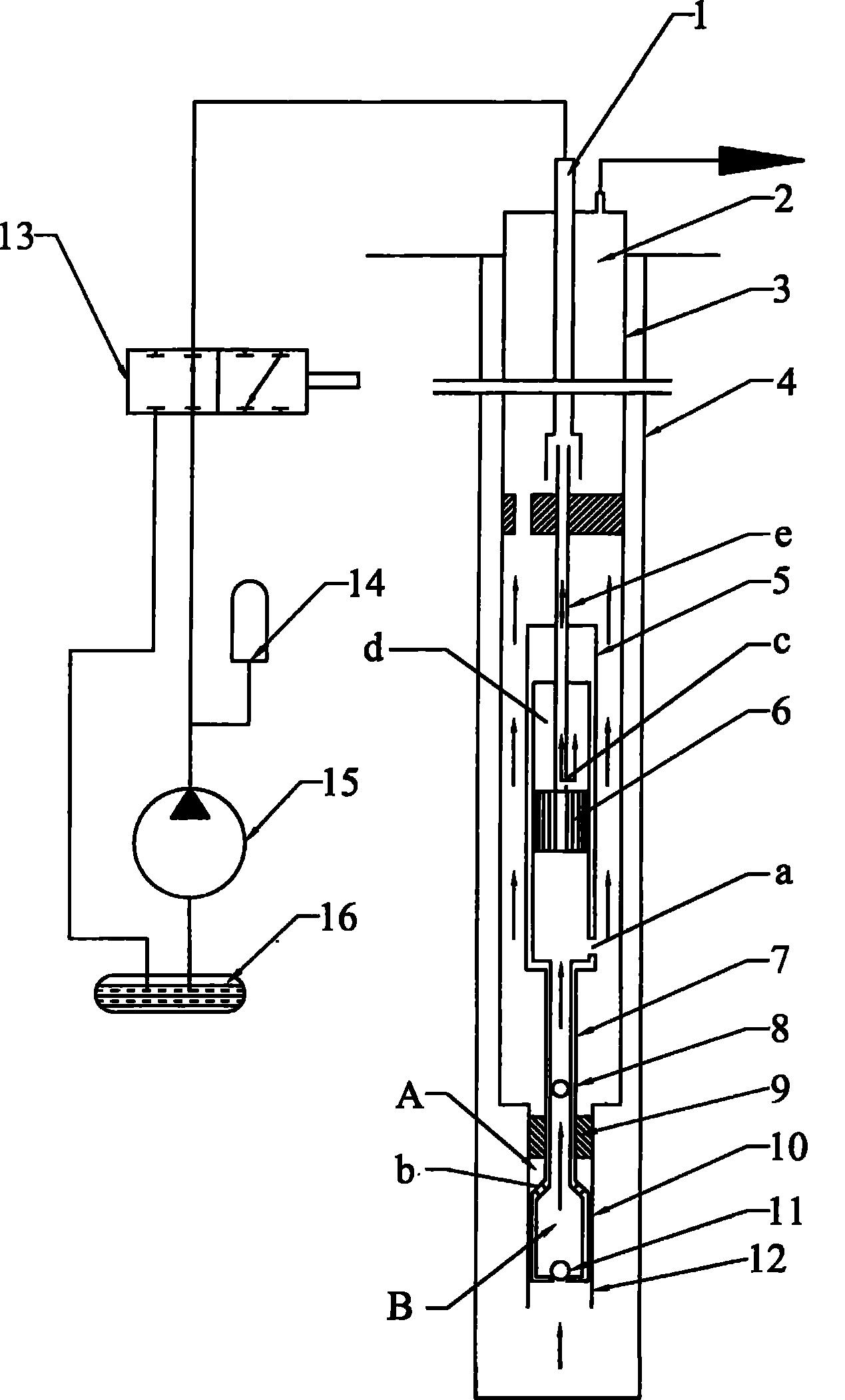
[0027] Such as figure 1 As shown, the oil well pump of the present invention is arranged in the casing 4 of the underground part, and is mainly composed of an oil pipe 3, a small pump barrel 9, and a large pump barrel 12 connected in series.
[0028] Wherein, the oil pipe 3 is provided with an upward pump barrel 5, the lower end of the upward pump barrel 5 is fixedly connected to a small plunger 7, and the lower end of the small plunger 7 is fixedly connected to a large plunger 10, and the inner cavities thereof are connected to each other. The small plunger 7 slides up and down in the small pump barrel 9, and the large plunger 10 slides up and down in the large pump barrel 12. A first oil port a is provided on the side wall of the upward pump barrel 5 near the small plunger 7. The inner cavity of the small plunger 7 is provided with an upper oil outlet...
PUM
Abstract
The invention relates to a hydraulic oil pump, which comprises an oil pipe 3, a small pump tube 9, a large pump tube 12, an up pump tube 5, a small plunger piston 7 and a large plunger piston 10, wherein the oil pipe 3, the small pump tube 9 and the large pump tube 12 are sequentially connected in series, the up pump tube 5, the small plunger piston 7 and the large plunger piston 10 are sequentially connected, the up pump tube 5 is arranged in the oil pipe 3, the side wall is provided with a first oil opening a, an inner cavity is provided with a fixed plunger piston 6, the up pump tube 5 makes up-down reciprocating movement outside the fixed plunger piston 6 through power liquid, the small plunger piston 7 makes up-down reciprocating movement inside the small pump tube 9, a second oil opening b is arranged at the joint of the small plunger piston 7 and the large plunger piston 10, the large plunger piston 10 makes up-down reciprocating movement inside the large pump tube 12, the bottom of the large plunger piston 10 is provided with a lower oil outlet valve 11, and the oil extraction is realized through the reciprocating movement of the up pump tube 5, the small plunger piston 7 and the large plunger piston 10 in the oil pipe 3, the small pump tube 9 and the large pump tube 12. The hydraulic oil pump of the invention has the advantages of large range of lower side depth, wide use range, safety, reliability, long service life, low use cost and the like.
Description
Technical field [0001] The invention relates to a hydraulically driven oil production equipment, in particular to an oil pump suitable for well wall bending deformation oil wells, highly deviated wells and horizontal wells, belonging to rodless oil production equipment. Background technique [0002] Conventional rod-type oil production equipment, although its efficiency is very low, has always been dominant in the world's petroleum industry due to its strong reliability and long service life. In recent years, with the development of drilling and oil production technologies, new conditions have emerged in oilfield production, with an increase in directional and horizontal wells. In addition, due to drilling errors in the early development process of the oilfield and formation creeping in the later production process, some oil well walls were severely bent and deformed, rods and tubes were eccentrically worn, and rods were frequently broken. [0003] For the above situation, the exi...
Claims
Application Information
Patent Timeline
Application Date:The date an application was filed.
Publication Date:The date a patent or application was officially published.
First Publication Date:The earliest publication date of a patent with the same application number.
Issue Date:Publication date of the patent grant document.
PCT Entry Date:The Entry date of PCT National Phase.
Estimated Expiry Date:The statutory expiry date of a patent right according to the Patent Law, and it is the longest term of protection that the patent right can achieve without the termination of the patent right due to other reasons(Term extension factor has been taken into account ).
Invalid Date:Actual expiry date is based on effective date or publication date of legal transaction data of invalid patent.