Connector

A technology of connectors and mating connectors, which is applied in the direction of connection, parts of connection devices, fixed/insulated contact members, etc., and can solve problems such as deterioration of the insertability of the retainer, excessive insertion resistance of the retainer, noise, etc.

Active Publication Date: 2011-03-30
SUMITOMO WIRING SYST LTD
View PDF5 Cites 10 Cited by
  • Summary
  • Abstract
  • Description
  • Claims
  • Application Information

AI Technical Summary

Problems solved by technology

However, in this structure, since the amount of contact of the restricting piece with the flat surface is large, the insertion resistance of the anchor becomes too large with multipolarization, and there is a problem that the insertability of the ancho...

Method used


Image

  • Connector
  • Connector
  • Connector

Examples


Embodiment approach 1

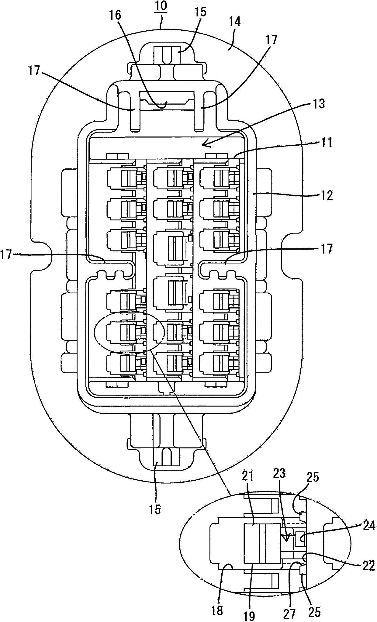
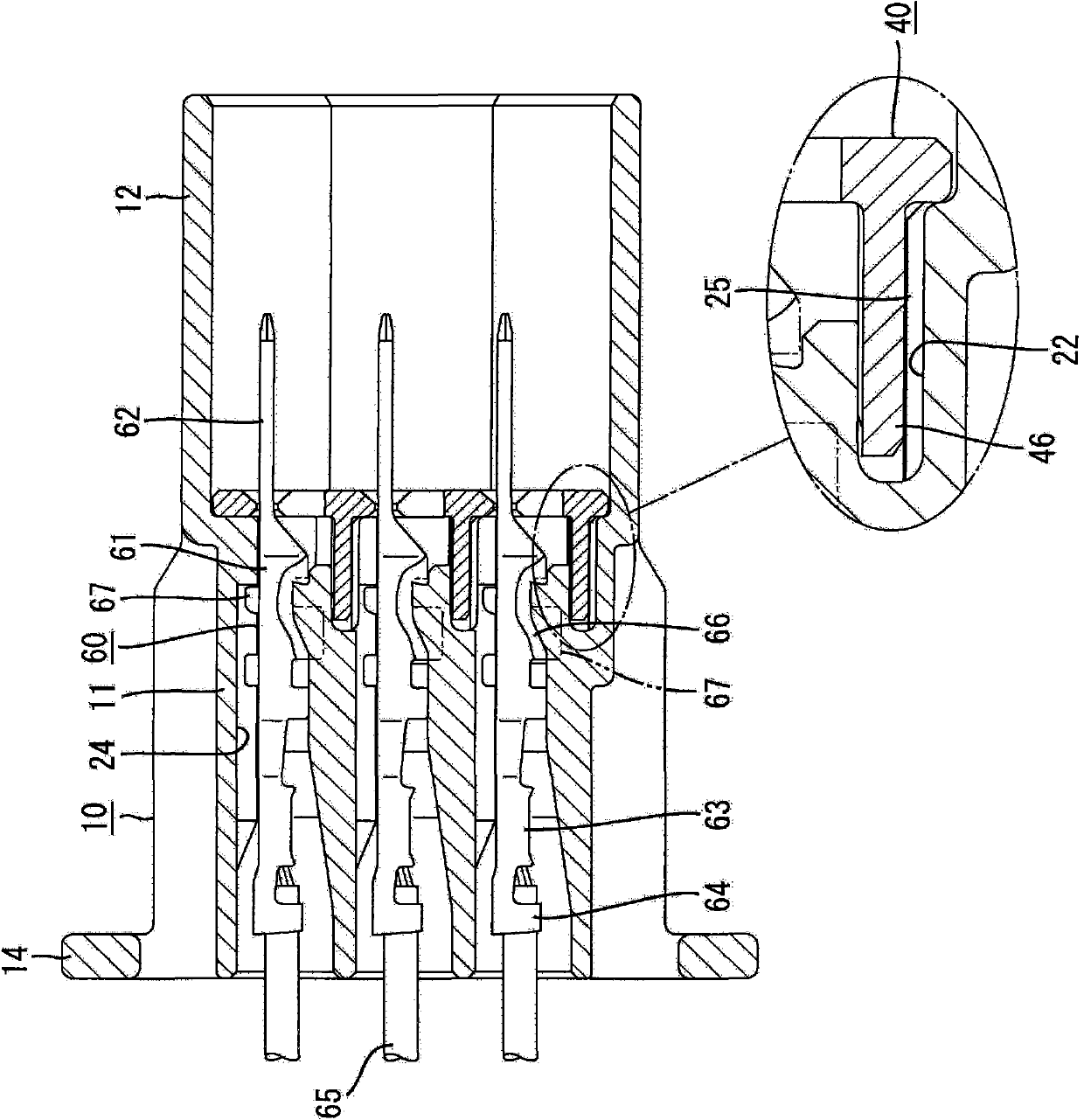
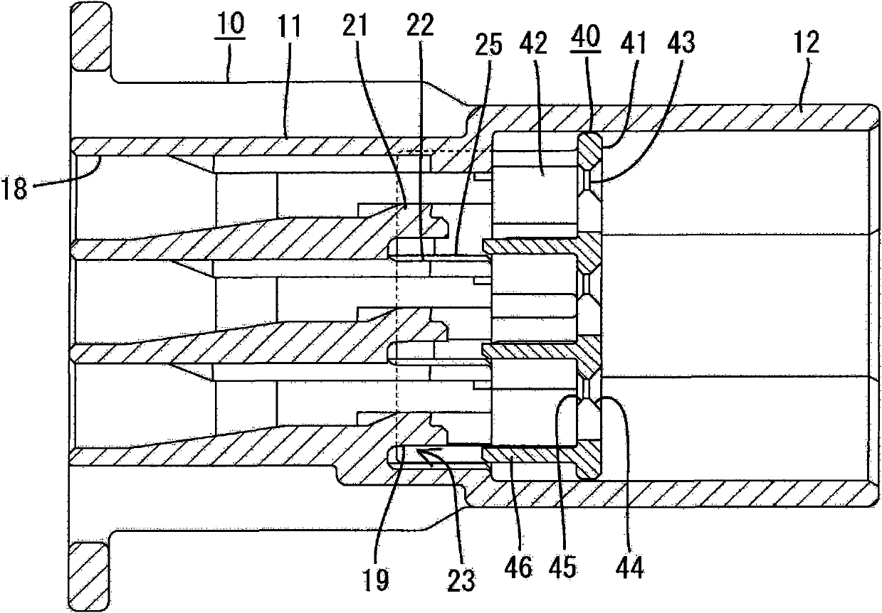
[0022] according to Figure 1 to Figure 6 Embodiment 1 of the present invention will be described. The connector of this embodiment includes a connector housing 10 , a holder 40 , and a male terminal fitting 60 , and the connector housing 10 can be fitted into a mating connector housing 80 . In addition, in the following description, regarding the front-rear direction, the mutual fitting surface side of both the connector housings 10 and 80 is defined as the front.

[0023] The mating connector housing 80 is made of synthetic resin, such as Figure 4 to Figure 6 As shown, it forms a vertically long block shape as a whole. On one side of the short side of the mating connector housing 80 is flexibly formed a lock arm 81 extending in the front-rear direction. The lock arm 81 is elastically engaged with the lock portion 16 formed on the connector housing 10 as the two connector housings 10 and 80 fit together, thereby maintaining the two connector housings 10 and 80 in a fitted...


PUM


Abstract

The present invention provides a connector, capable of preventing insertion resistance of a fixer from oversize and preventing the fixer from loosening. A housing (10) of the connector is provided with a flexible spear-shaped member (19), and the fixer (40) is mounted thereon. The fixer (40) is provided with a spacing sheet (46) for limiting elastic deflection of the spear-shaped member (19) by entering a flexible space (23) of the spear-shaped member (19). An opposite surface (22) is provided with a plurality of projections (25) in a flexible direction of the spear-shaped member (19) of the housing (10), the projections are abutted with the spacing sheet (46) which enters the flexible space (23) to clip the spacing sheet (46) between the projections and the spear-shaped member (19). Eachprojection (25) is arranged in a position on the opposite surface (22) away from a projection range of the spear-shaped member (19).

Description

technical field [0001] The invention relates to a connector. Background technique [0002] Patent Document 1 discloses a prior art connector. The connector includes a connector housing having a cavity into which a terminal fitting can be inserted. A flexible lance is formed on the inner surface of the cavity of the connector housing, and the terminal fitting normally inserted into the cavity is elastically prevented from being pulled out by the lance. In addition, a fixer having a restricting piece that restricts elastic deflection of the lance by entering the deflection space of the lance is mounted on the connector housing. The terminal fitting is double locked by the lance and the retainer, thereby reliably preventing it from being pulled out of the cavity. [0003] Patent Document 1: Japanese Patent Laid-Open No. 2003-243081 [0004] However, in the case of the above-mentioned prior art connector, the inner surface of the connector housing opposed to the lance is a f...

Claims


Application Information

Patent Timeline
IPC IPC(8): H01R13/42H01R13/426
Inventor 郑松
Owner SUMITOMO WIRING SYST LTD
Why Eureka
Try Eureka