Air conditioner

An air-conditioning device and heat medium technology, applied in air-conditioning systems, household refrigeration devices, cooling fluid circulation devices, etc., can solve problems such as the deterioration of the indoor environment, and achieve the effect of improving reliability

Active Publication Date: 2011-06-22
MITSUBISHI ELECTRIC CORP
View PDF17 Cites 9 Cited by
  • Summary
  • Abstract
  • Description
  • Claims
  • Application Information

AI Technical Summary

Problems solved by technology

[0006] In the conventional air conditioner, since refrigerant such as HFC is sent to the indoor unit for utilization, there is a problem that the indoor environment deteriorates when the refrigerant leaks into the room.

Method used


Image

  • Air conditioner
  • Air conditioner
  • Air conditioner

Examples


Embodiment approach 1

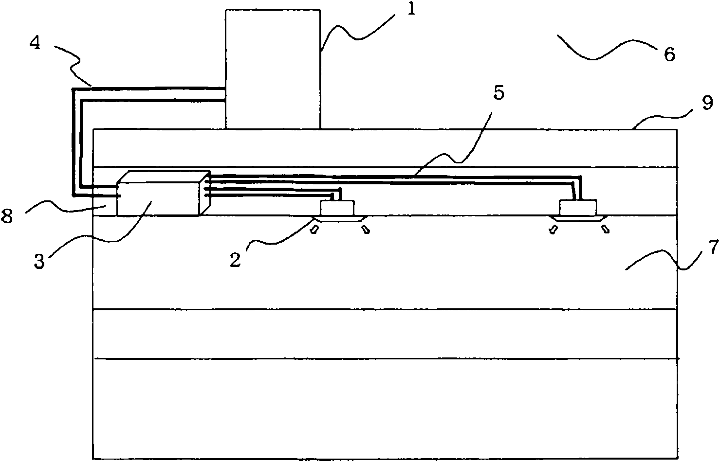
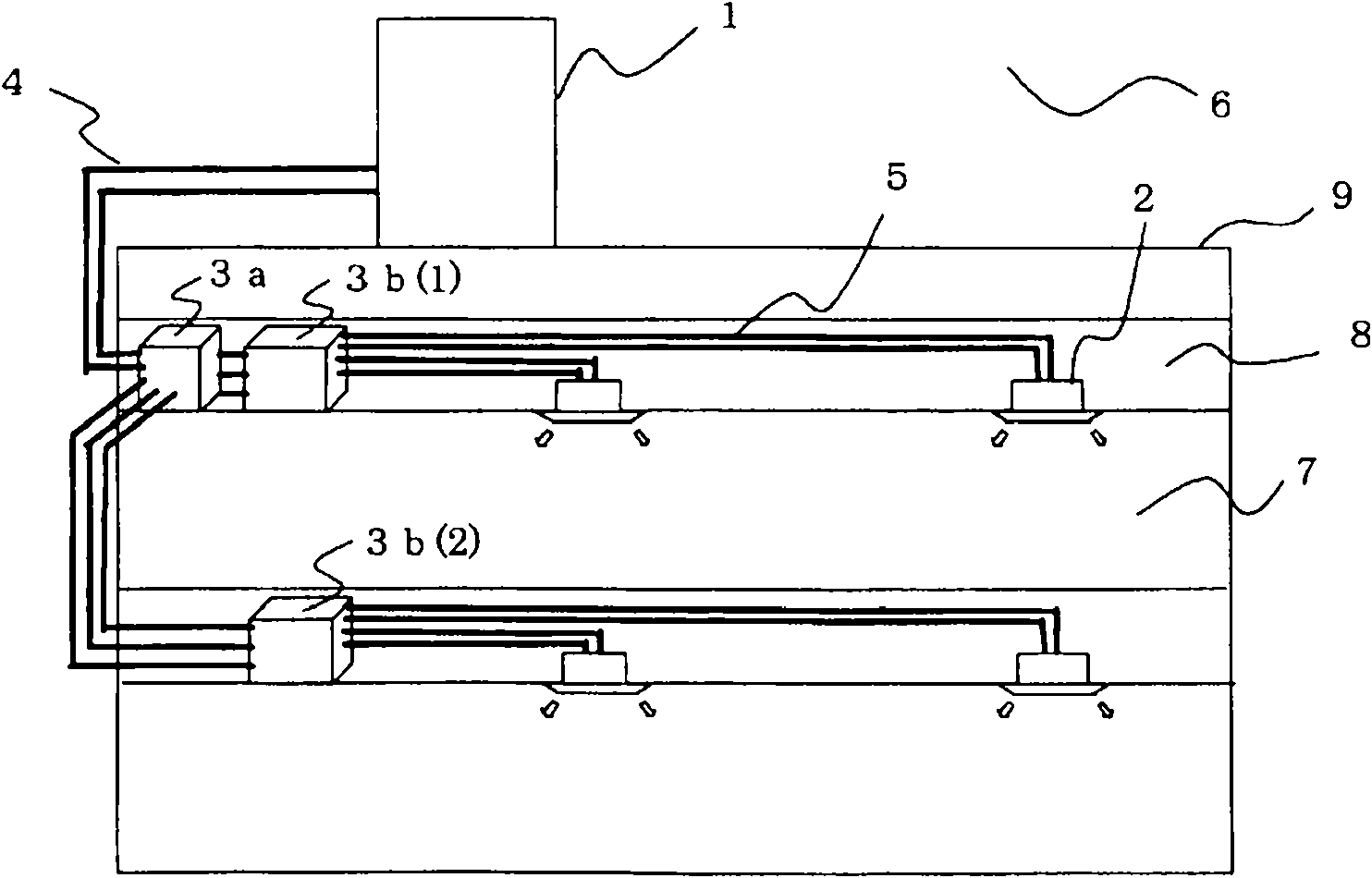
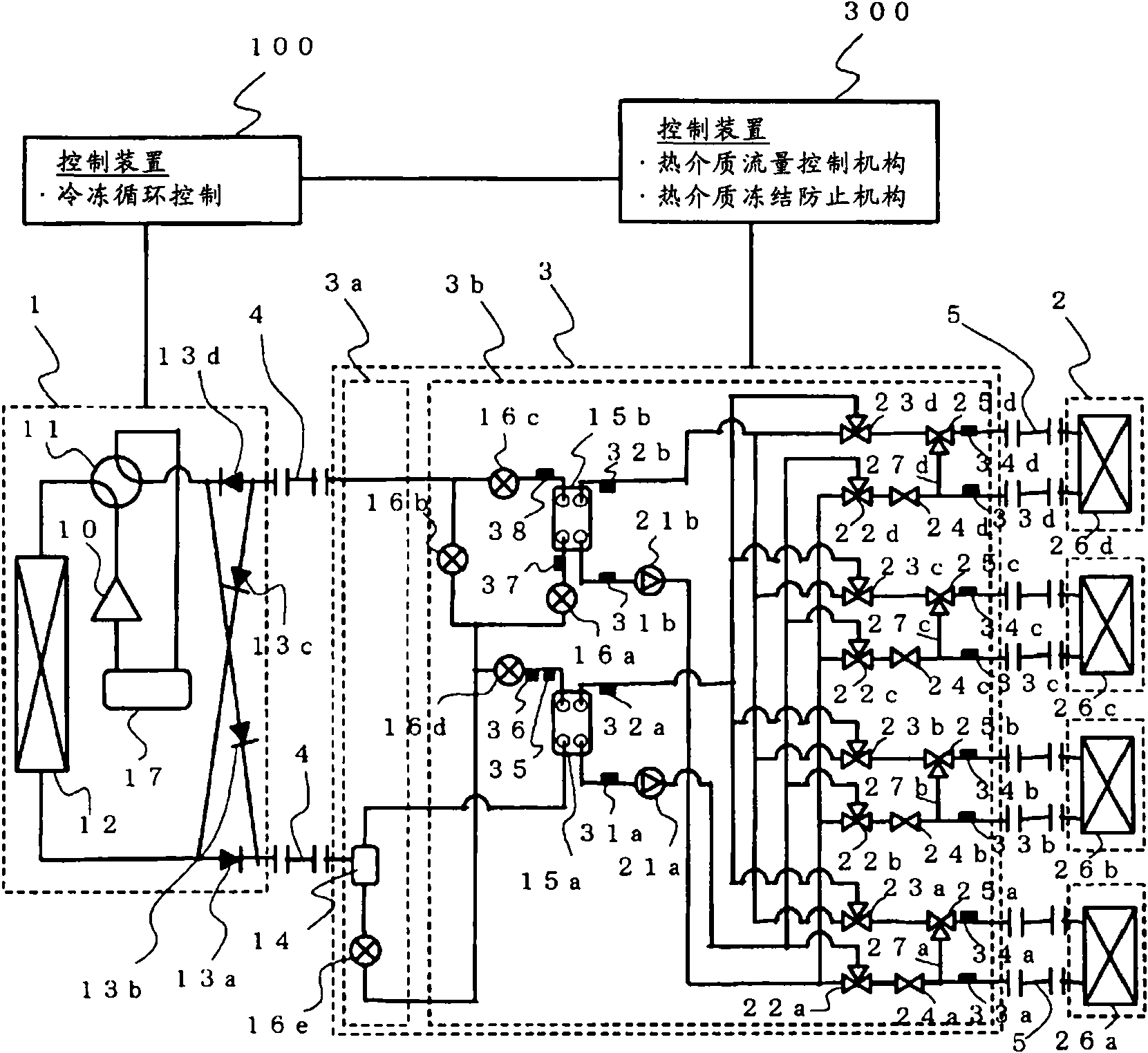
[0033] figure 1 , figure 2 It is an overall configuration diagram of the air conditioner according to Embodiment 1 of the present invention. This air conditioner includes a heat source device (outdoor unit) 1, an indoor unit 2 for air conditioning indoors, etc., and a relay unit 3 installed in a non-air-conditioned space 8 or the like away from the outdoor unit 1 . The heat source device 1 and the relay unit 3 are connected by a refrigerant pipe 4 through which a two-phase refrigerant or a supercritical state refrigerant (primary medium) flows. The relay unit 3 and the indoor unit 2 are connected by a pipe 5 through which a heat medium (secondary medium) such as water, brine, or antifreeze flows. The relay unit 3 performs heat exchange and the like between the refrigerant sent from the heat source device 1 and the heat medium sent from the indoor unit 2 .

[0034] The heat source device 1 is usually disposed in an outdoor space 6 which is an external space of a building 9 ...


PUM


Abstract

An air conditioner in which a heat source-side heat exchanger (12), an intermediate heat exchanger (15a, 15b), and a utilization-side heat exchanger (26a-26d) are respectively formed as separate bodies and adapted so that they can be placed at positions separated from each other. Temperature sensors (31, 32, 33, 34) are arranged in a heat medium circulation circuit to which the intermediate heat exchanger and the utilization-side heat exchanger are connected. The air conditioner has a freeze prevention operation mode which, when the temperature detected by the temperature sensors (31, 32, 33,34) becomes lower than or equal to a pre-set temperature (Ts) while the compressor (10) is at a stop or a pump (21a-21d) is at a stop, circulates the heat medium to prevent the heat medium from freezing.

Description

technical field [0001] The invention relates to air-conditioning devices such as multi-type air conditioners for buildings. Background technique [0002] In a multi-type air conditioner for buildings as a conventional air conditioner, cooling or heat is sent indoors by circulating refrigerant between an outdoor unit as a heat source device disposed outdoors and an indoor unit disposed indoors. As a refrigerant, HFC (hydrofluorocarbon) refrigerants are often used, and the use of CO 2 and other natural refrigerants. [0003] In addition, in a refrigerator as another conventional air conditioner, cooling or heat is generated by a heat source device disposed outdoors, and the cooling or heat is transferred to water, antifreeze, etc. by a heat exchanger disposed in the outdoor unit. The heat medium is sent to a fan coil unit or a panel heater as an indoor unit to perform cooling or heating (for example, refer to Patent Document 1). [0004] Patent Document 1: Japanese Patent L...

Claims


Application Information

Patent Timeline
Patent Type & Authority Applications(China)
IPC IPC(8): F24F11/02F25B1/00F25B13/00F25B29/00
CPCF24F2011/0087F24F11/0012F25B47/006F25B2313/006F25B2313/0233F24F2011/0045F25B13/00F25B2313/0314F24F3/06F25B2313/0272F25B2313/0232F25B25/005F25B2313/02741F25B2313/0231F24F11/30F24F2110/10F24F2110/12F24F2140/20F24F11/83F24F11/41F24F11/85F24F11/84F25D17/02
Inventor 山下浩司森本裕之本村祐治鸠村杰
Owner MITSUBISHI ELECTRIC CORP
Why Eureka
Try Eureka