Turbine

A turbine and cam technology, applied in the direction of engines, mechanical equipment, engine components, etc., can solve the problems of limited service life, short service life of power conversion units, etc., and achieve the effect of simple design and high efficiency

Inactive Publication Date: 2011-09-21
DUTCH RAINMAKER BV
View PDF12 Cites 3 Cited by
  • Summary
  • Abstract
  • Description
  • Claims
  • Application Information

AI Technical Summary

Problems solved by technology

In this way, the power conversion unit has a too short service life, since the power conversion unit switched on at low speed starts limits the service life of the entire device

Method used


Image

  • Turbine
  • Turbine
  • Turbine

Examples


Embodiment Construction

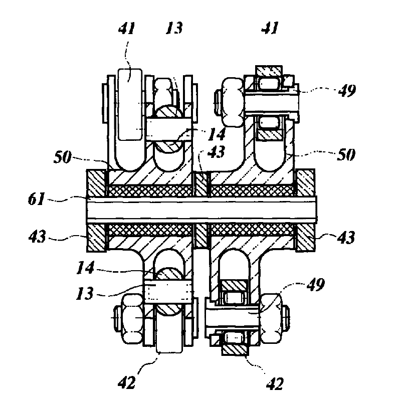
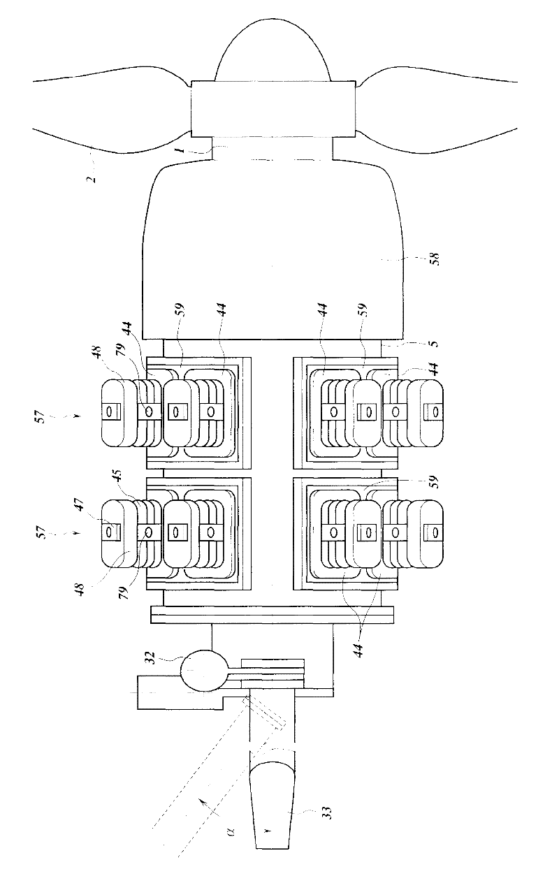
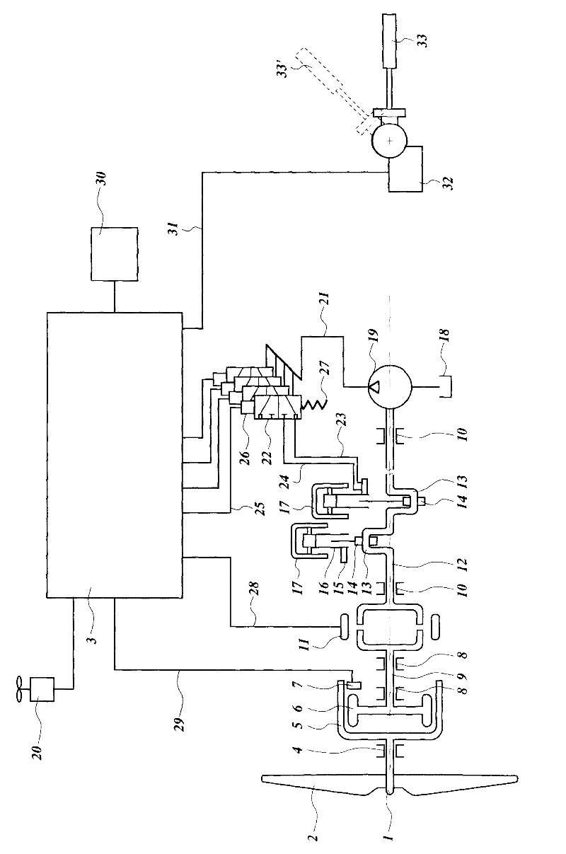
[0033] figure 1 A functional block diagram of a wind turbine with turbine blades 2 coupled to a turbine shaft 1 rotating in a bearing 4 of the turbine shaft is shown. A turbine shaft 1 of a wind turbine has an outer coupling half 5 which rotates an inner coupling half 6 mounted to a coupling shaft 9 which rotates in a bearing 8 of the coupling shaft. A switchable coupling 11 couples the coupling shaft 9 to the compressor shaft 12 . The compressor shaft 12 rotates in compressor shaft bearings 10 and drives a pump 19 , and has a crank pin 13 coupled to an inner connecting rod 14 . Each inner connecting rod 14 has a connecting rod coupling 15 for coupling the inner connecting rod 14 to an outer connecting rod 16 . The outer connecting rod 16 is fastened to a piston 17 which is reciprocally movable within the cylinder and thus compresses the refrigerant.

[0034] The control system 3 is designed to control the settings of the refrigerant compressor. The control system 3 is cou...


PUM


Abstract

The present invention concerns a turbine driving a power conversion means, the power conversion means comprising several power conversion units, preferably of approximately similar power conversion capacity, that have coupling means for coupling the power conversion units to the turbine, the turbine having measuring means for determining the rotation speed of the turbine and / or a flow speed of the turbine driving flow of wind or water and a control system for controlling the coupling means in dependence of the determined rotation speed and / or flow speed. In accordance with the invention the control system has means for activating and deactivating the coupling means for the different the power conversion units so that the power conversion units are used equally.

Description

Background technique [0001] The invention relates to a turbomachine according to the preamble of claim 1 . Such a turbine is known, for example, from DE 601986. This document shows a wind turbine driving several compressors for compressing gas. The number of compressor units running and the torque drawn from the wind turbine vary depending on the rotational speed of the wind turbine. However, the compressor units are switched on sequentially in a fixed order. This leads to wear of the power conversion unit, in this case the compressors switched on at low rotational or flow speeds are worn out because they are used much more frequently than the other units. For example, a power conversion unit switched on at high speed will have little wear. In this way, the power conversion unit has a too short service life, since switching on the power conversion unit at low speed starts limits the service life of the entire device. Contents of the invention [0002] In order to overco...

Claims


Application Information

Patent Timeline
IPC IPC(8): F04B35/00F03D9/00
CPCY02E60/15F03D9/028F04B2201/0807Y02E10/725F04B35/00Y02E10/72F05B2210/16F03D9/17F03D9/25F03D9/28Y02E60/16Y02P80/10Y02E70/30
Inventor P.乌斯特林
Owner DUTCH RAINMAKER BV
Why Eureka
Try Eureka