Radio terminal device, radio base station device, and channel signal forming method

A wireless terminal, channel signal technology, applied in the direction of wireless communication, transmission path separation device, transmission path sub-channel allocation, etc., to achieve the effect of preventing quality degradation

Active Publication Date: 2011-09-28
SUN PATENT TRUST
View PDF5 Cites 4 Cited by
  • Summary
  • Abstract
  • Description
  • Claims
  • Application Information

AI Technical Summary

Problems solved by technology

However, LTE terminals can only receive one unit frequency band at the same time

Method used


Image

  • Radio terminal device, radio base station device, and channel signal forming method
  • Radio terminal device, radio base station device, and channel signal forming method
  • Radio terminal device, radio base station device, and channel signal forming method

Examples


Embodiment approach 1

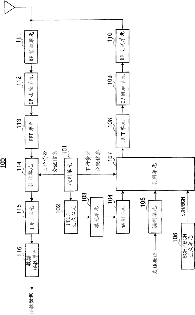
[0043] figure 2 It is a block diagram showing the configuration of base station 100 according to Embodiment 1 of the present invention. exist figure 2 Among them, the base station 100 has a control unit 101, a PDCCH generation unit 102, a padding unit 103, modulation units 104, 105, an SCH / BCH generation unit 106, a multiplexing unit 107, an IFFT unit 108, a CP addition unit 109, an RF transmission unit 110, RF receiving unit 111 , CP removing unit 112 , FFT unit 113 , extracting unit 114 , IDFT unit 115 and data receiving unit 116 . The base station 100 is configured to be able to perform communication using an uplink component frequency band and a plurality of downlink component frequency bands associated with the uplink component frequency band.

[0044] The control unit 101 generates uplink resource allocation information and downlink resource allocation information for the terminal 200 described later, outputs the uplink resource allocation information to the PDCCH ge...

Embodiment approach 2

[0095] When the bandwidth of the uplink component frequency band is the same as that of the downlink component frequency band, sometimes the sizes of the downlink resource allocation information and the uplink resource allocation information are different from each other. The only difference between this embodiment and Embodiment 1 is that at this point.

[0096] That is, in Embodiment 1, it was explained that if the bandwidth of the uplink component frequency band and the bandwidth of the downlink component frequency band are the same, the downlink resource allocation information of the downlink component frequency band in the basic component frequency band has the same information size as the uplink resource allocation information . On the other hand, in this embodiment, when the bandwidth of the uplink component frequency band is the same as that of the downlink component frequency band, the information sizes of the downlink resource allocation information and the uplink re...

Embodiment approach 3

[0119] This embodiment differs from Embodiments 1 and 2 in that the base station variably sets the basic unit frequency band for each terminal.

[0120] That is, in Embodiment 3, the base station sets a basic component frequency band according to the same criteria as in Embodiment 1 or 2 when starting high-speed communication with a certain terminal by carrier aggregation. However, in Embodiment 3, the base station can instruct the terminal to add / change the basic component band at any timing.

[0121] Below, use Figure 5 to Figure 9 Next, each configuration and operation of the base station 300 and the terminal 400 according to Embodiment 3 of the present invention will be specifically described.

[0122] Figure 5 It is a block diagram showing the configuration of base station 300 according to Embodiment 3 of the present invention. and figure 2 Shown in base station 100 compared to the Figure 5 The base station 300 shown has a control unit 301 instead of the control ...


PUM


Abstract

Provided are a radio terminal device, a radio base station device, and a channel signal forming method which can prevent quality degradation of the downlink source allocation information by reducing the frequency of the zero information addition process to the downlink resource allocation information when executing communication using an uplink unit band and a plurality of downlink unit bands correlated to the uplink unit band. A base station (100) can execute communication using the uplink unit band and a plurality of downlink unit bands correlated to the uplink unit band. The base station (100) includes: a PDCCH generation unit (102) which includes the uplink allocation information relating to the uplink unit band only in some of the channel signals formed for each of the downlink unit bands; and a padding unit (103) which adds zero information to the downlink allocation information only in the selected some channel signals having the bandwidth of the corresponding downlink unit band smaller than that of the uplink unit band until the downlink allocation information size becomes equal to the uplink allocation information size.

Description

technical field [0001] The present invention relates to a wireless terminal device, a wireless base station device, and a channel signal forming method. Background technique [0002] In 3GPP LTE, OFDMA (Orthogonal Frequency Division Multiple Access, Orthogonal Frequency Division Multiple Access) is adopted as a downlink communication method. In a wireless communication system to which 3GPP LTE is applied, a base station transmits a synchronization signal (Synchronization Channel: SCH) and a broadcast signal (Broadcast Channel: BCH) using predetermined communication resources. And, the terminal first ensures synchronization with the base station by acquiring the SCH. Then, the terminal acquires base station-specific parameters (for example, bandwidth, etc.) by reading BCH information (see Non-Patent Documents 1, 2, and 3). [0003] In addition, after the terminal acquires the parameters unique to the base station, it sends a connection request to the base station, thereby e...

Claims


Application Information

Patent Timeline
Patent Type & Authority Applications(China)
IPC IPC(8): H04W28/06H04J11/00H04W72/04H04J1/00
CPCH04L5/0094H04L5/0007H04L1/004H04W28/06H04W72/042H04W72/0453H04L5/003H04W72/23H04L5/0053H04L5/001H04L5/0046
Inventor 中尾正悟西尾昭彦今村大地青山高久
Owner SUN PATENT TRUST
Why Eureka
Try Eureka