Integrated continuous gas-driving hydraulic force booster

A booster device and gas-hydraulic booster cylinder technology, which is applied in the hydraulic and pneumatic fields, can solve the problems of complex structure of the gas-hydraulic booster cylinder, low efficiency of the booster cylinder, and inability to realize automatic reversing, etc., to achieve compact structure, large Boosting ratio, the effect of a large boosting ratio

Active Publication Date: 2014-06-25
TONGJI UNIV
View PDF8 Cites 0 Cited by
  • Summary
  • Abstract
  • Description
  • Claims
  • Application Information

AI Technical Summary

Problems solved by technology

[0002] At present, the gas-liquid booster cylinder is generally single-acting, and half of the working cycle of the single-acting gas-liquid booster cylinder is used to absorb oil from the fuel tank, and only half of the time is used to effectively supply oil to the outside world. Therefore, the efficiency of the single-acting booster cylinder is generally low; although there are also double-acting gas-liquid booster cylinders on the market, some of these existing double-acting gas-liquid booster cylinders cannot realize automatic reversing, and some Although it can realize automatic reversing, its reversing principle is realized by using a mechanical method (such as the piston touching the travel switch at the end of the stroke) to feed back the stroke signal and then control the reversing valve to reversing. Using this reversing method The structure of the gas-liquid booster cylinder is more complex

Method used


Image

  • Integrated continuous gas-driving hydraulic force booster
  • Integrated continuous gas-driving hydraulic force booster
  • Integrated continuous gas-driving hydraulic force booster

Examples


Embodiment Construction

[0024] The present invention will be further described below in conjunction with the embodiments shown in the accompanying drawings.

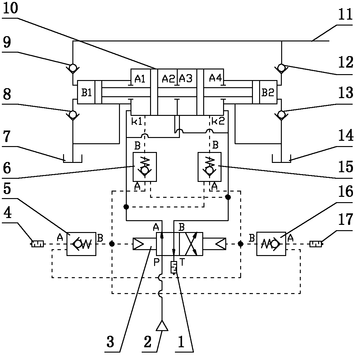
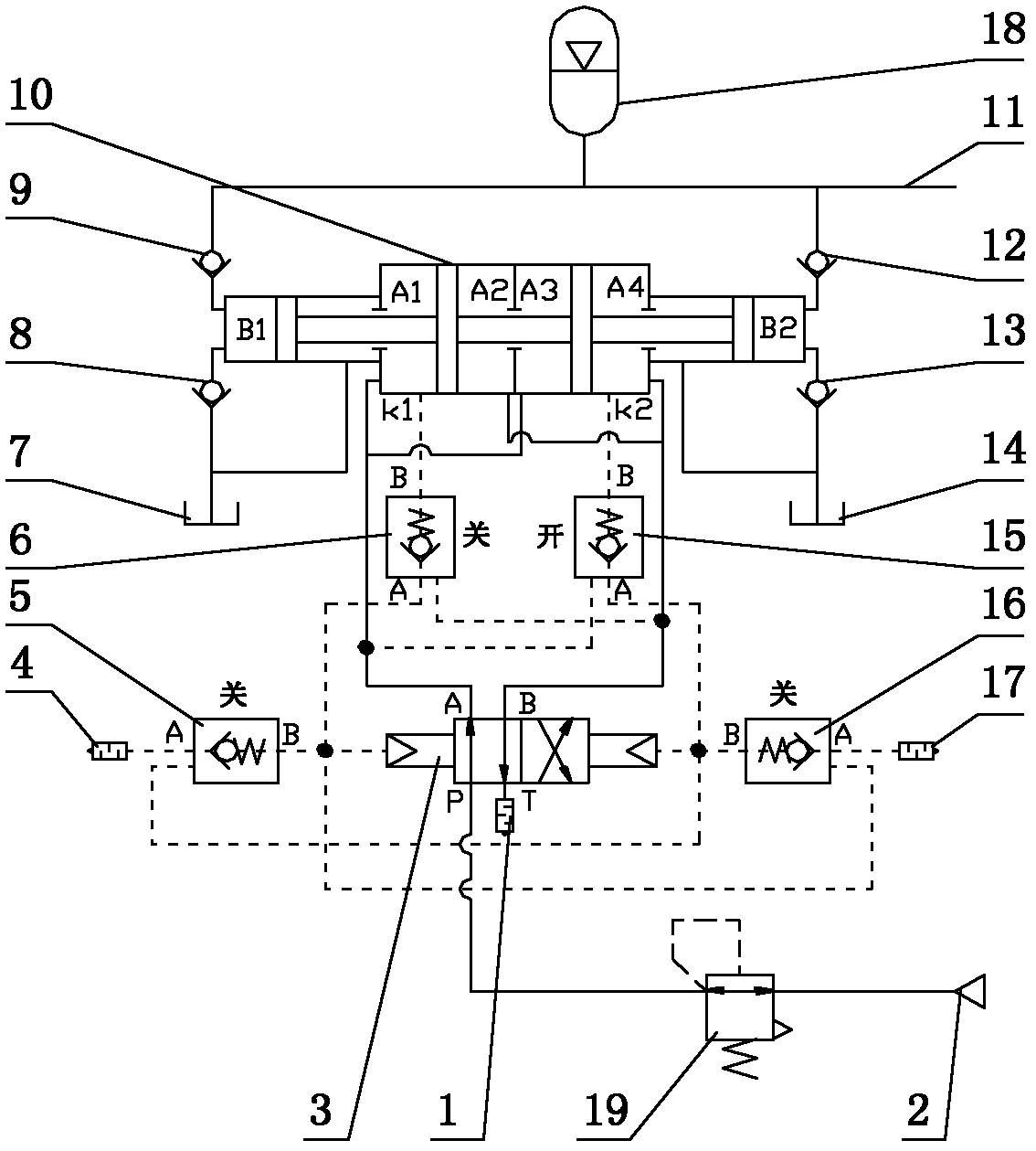
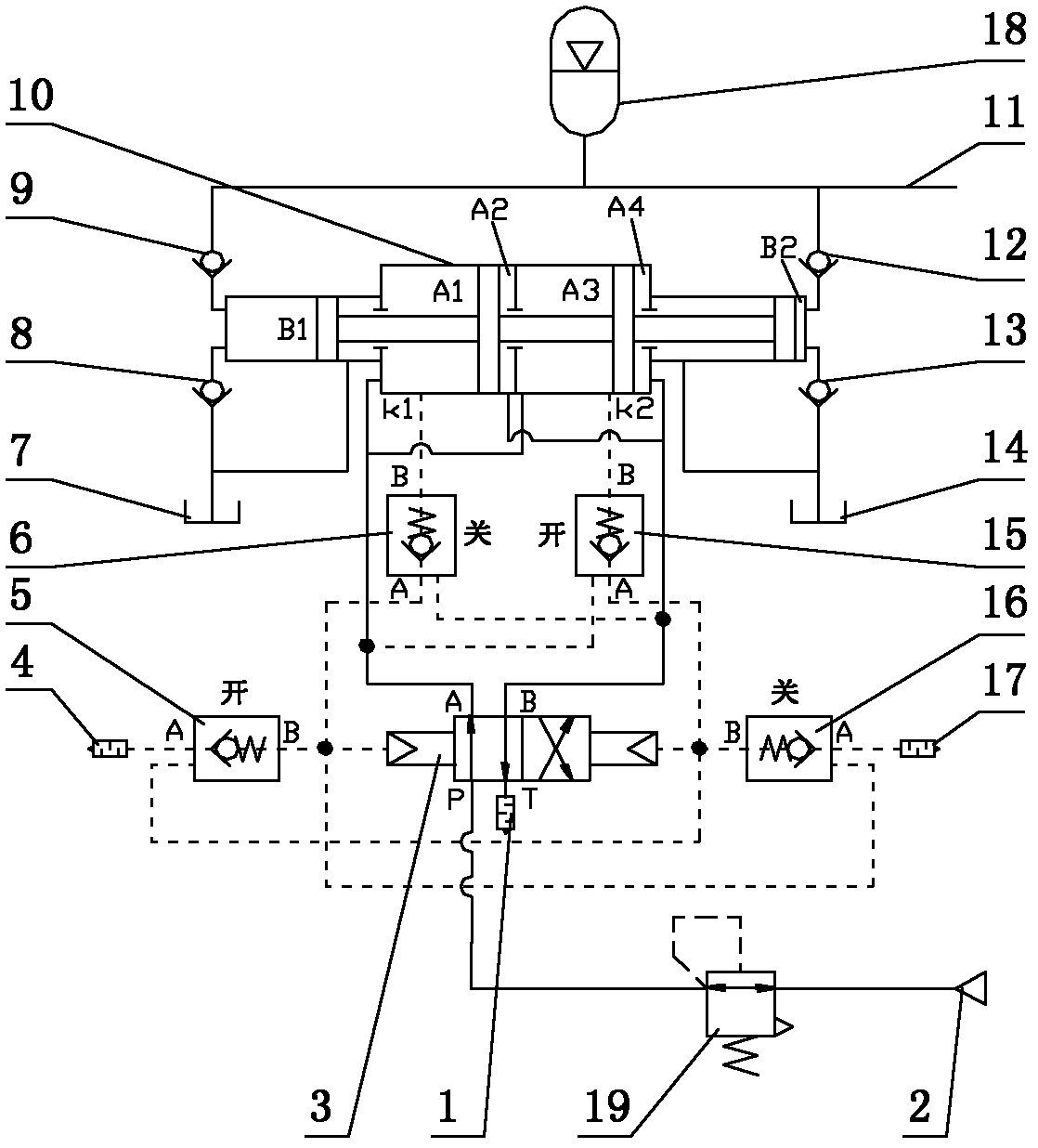
[0025] The connection mode of the present invention is: an integrated continuous air-driven hydraulic booster device, which consists of a gas-liquid booster cylinder 10, a hydraulic check valve 8, 9, 12, 13, a two-position four-way air-controlled reversing valve 3, an air-controlled Check valve 5,6,15,16, muffler 1,4,17 etc. are formed. Among them, the gas-liquid booster cylinder is a double-acting booster cylinder, and two large pistons and two small pistons are installed on the piston rod; the two small pistons and the cylinder body form two oil chambers B1 and B2; The piston and the cylinder form four air chambers A1, A2, A3, A4, and there are two stroke signal ports k1, k2 in the middle of the two air chambers on both sides, and the stroke signal ports k1, k2 are used for feedback booster cylinder 10 The stroke information of the piston an...


PUM


Abstract

The invention discloses an integrated continuous gas-driving hydraulic force booster, comprising a gas-liquid boosting cylinder, a hydraulic check valve, a two-position four-way pneumatic control reversing valve, a pneumatic check valve and a silencer, wherein the gas-liquid boosting cylinder is a double-action boosting cylinder; two big pistons and two small pistons are arranged on a piston rod of the gas-liquid boosting cylinder; the two small pistons and the cylinder body form two oil cavities; the two big pistons and the cylinder body form four air cavities; and the middles of the two air cavities on two sides are provided with two travel signal ports. If the pistons and the piston rods of the boosting cylinder move rightwards, the travel information of the pistons and the piston rod is fed back to the reversing valve to cause the reversing valve to reverse by the control of the pneumatic check valve in the mode of pressure air mode when the right big piston crosses the right travel signal port; the pistons and the piston rod of the boosting cylinder can be reversed because of the reversal of the pneumatic control reversing valve; and thus, the pistons and the piston rod of the boosting cylinder can be automatically reversed on the tail end of the travel of the pistons and the piston rod. The device disclosed by the invention has the advantages of compact structure and big supercharge ratio, automatic reversal can be realized, and uninterrupted oil supply can be realized.

Description

technical field [0001] The invention belongs to the technical field of hydraulic pressure and pneumatics, and relates to a gas-hydraulic booster, in particular to an integrated continuous gas-driven hydraulic booster. Background technique [0002] At present, the gas-liquid booster cylinder is generally single-acting, and half of the working cycle of the single-acting gas-liquid booster cylinder is used to absorb oil from the fuel tank, and only half of the time is used to effectively supply oil to the outside world. Therefore, the efficiency of the single-acting booster cylinder is generally low; although there are also double-acting gas-liquid booster cylinders on the market, some of these existing double-acting gas-liquid booster cylinders cannot realize automatic reversing, and some Although it can realize automatic reversing, its reversing principle is realized by using a mechanical method (such as the piston touching the travel switch at the end of the stroke) to feed ...

Claims


Application Information

Patent Timeline
Patent Type & Authority Patents(China)
IPC IPC(8): F15B3/00
Inventor 左建勇罗卓军
Owner TONGJI UNIV
Why Eureka
Try Eureka