Connecting unit

A technology for connecting units and connectors, which is applied in the direction of connection, conductive connection, electrical connection of printed components, etc., and can solve problems such as not being able to ensure enough space

Active Publication Date: 2012-01-25
YAZAKI CORP
View PDF4 Cites 0 Cited by
  • Summary
  • Abstract
  • Description
  • Claims
  • Application Information

AI Technical Summary

Problems solved by technology

In addition, in order to connect the L-shaped terminals 104 to the plurality of through holes 103, respectively, the L-shaped terminals 104 (104a to 104c) of different heights (h1 to h3) are arranged at the terminal connection area 101a, so that the L-shaped terminals 104 (104a to 104c) are densely arranged, and therefore, a sufficient space for forming the circuit layout 102 cannot be secured at the terminal connection region 101a.

Method used


Image

  • Connecting unit
  • Connecting unit
  • Connecting unit

Examples


Embodiment Construction

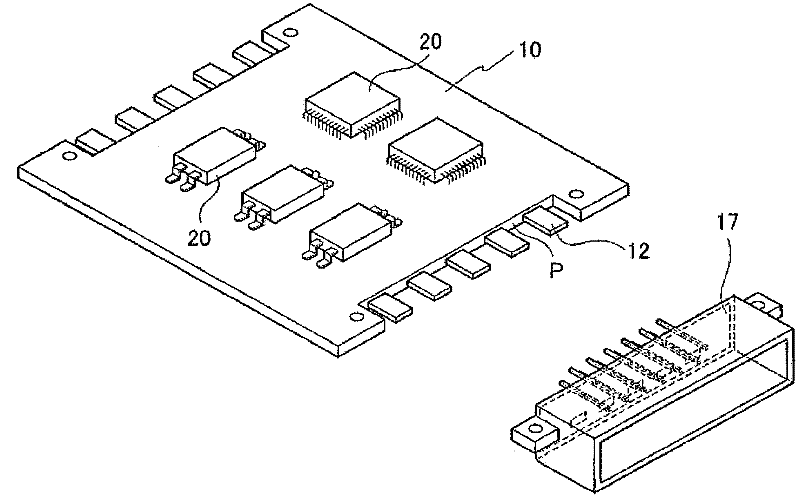
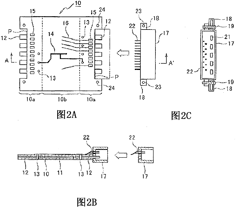
[0064] Preferred embodiments of the present invention will now be described with reference to the accompanying drawings. figure 1 is a perspective view showing a connector connection structure of a wiring board according to a preferred embodiment of the present invention, and 2A, 2B and 2C are a plan view, a front view (along line A-A) of a connector connection structure of the wiring board, respectively. 'Intercepted sectional view) and side view.

[0065] As shown in the drawing, the wiring board 10 of this embodiment has a generally rectangular shape as a whole, and each of the left end and the right end (in the drawing) of the wiring board 10 is notched to form a recess, and is notched The inner side (edge) of the portion (that is, the bottom of the concave portion) is formed as a linear side edge P. Such as figure 1 As shown, various electronic components 20 are mounted on the surface of the wiring board 10 .

[0066] Such as Figure 2A As shown, the left and right ...


PUM


Abstract

A connecting unit includes a wiring board (10) and a connector (17). The wiring board has a main face and a side face substantially perpendicular to the main face, and includes a metal plate (11) and a first terminal (12). The connector has a through hole (21) for passing the first terminal therethrough. The first terminal is disposed in an intermediate layer of the wiring board and is projected outwardly from the side face. When the connector is connected to the wiring board, the first terminal passes through the through hole.

Description

technical field [0001] The present invention relates to a wiring board having a vapor chamber (radiation plate), and more particularly to a connection unit for connecting a connector to the wiring board. Background technique [0002] For example, regarding a wiring board for mounting on a vehicle, such a wiring board is widely used in which a connector is connected to a side edge portion of the wiring board and the wiring board is connected to a wire harness through the connector (see, for example Patent Document 1). Image 6 is a perspective view showing a conventional wiring board connector connection structure, Figure 7A is its floor plan, Figure 7B is its front view (sectional view taken along the line B-B'), and Figure 7C is its side view. Such as Figure 7A As shown, on the surface of the wiring board 101, a large current circuit layout 102a and a small current circuit layout 102b are formed. In this wiring board 101 , left and right regions (in the drawing) ar...

Claims


Application Information

Patent Timeline
Patent Type & Authority Applications(China)
IPC IPC(8): H05K1/11H05K3/40H01R12/00H01R12/55H01R12/71H01R12/72H01R12/77H01R24/60
CPCH05K2201/0352H05K2201/0397H01R12/721H05K1/117H01R12/714H05K2201/10189H05K3/202H05K1/0263H05K3/4092H01R9/091H05K2201/10446
Inventor 泽井守
Owner YAZAKI CORP
Why Eureka
Try Eureka