
Hammering tool
A technology of impact tools and shells, which is applied in the field of impact tools, can solve problems such as poor workability and damage, and achieve the effects of improving reliability, maintaining miniaturization, and good operability
- Summary
- Abstract
- Description
- Claims
- Application Information
AI Technical Summary
Problems solved by technology
Method used
Image

Examples
Embodiment Construction
[0044] Embodiments of the present invention will be described below based on the drawings. In addition, in the form after form 2, the same code|symbol is attached|subjected to the structural part common to form 1, and the overlapping description is abbreviate|omitted.
[0045] [Method 1]
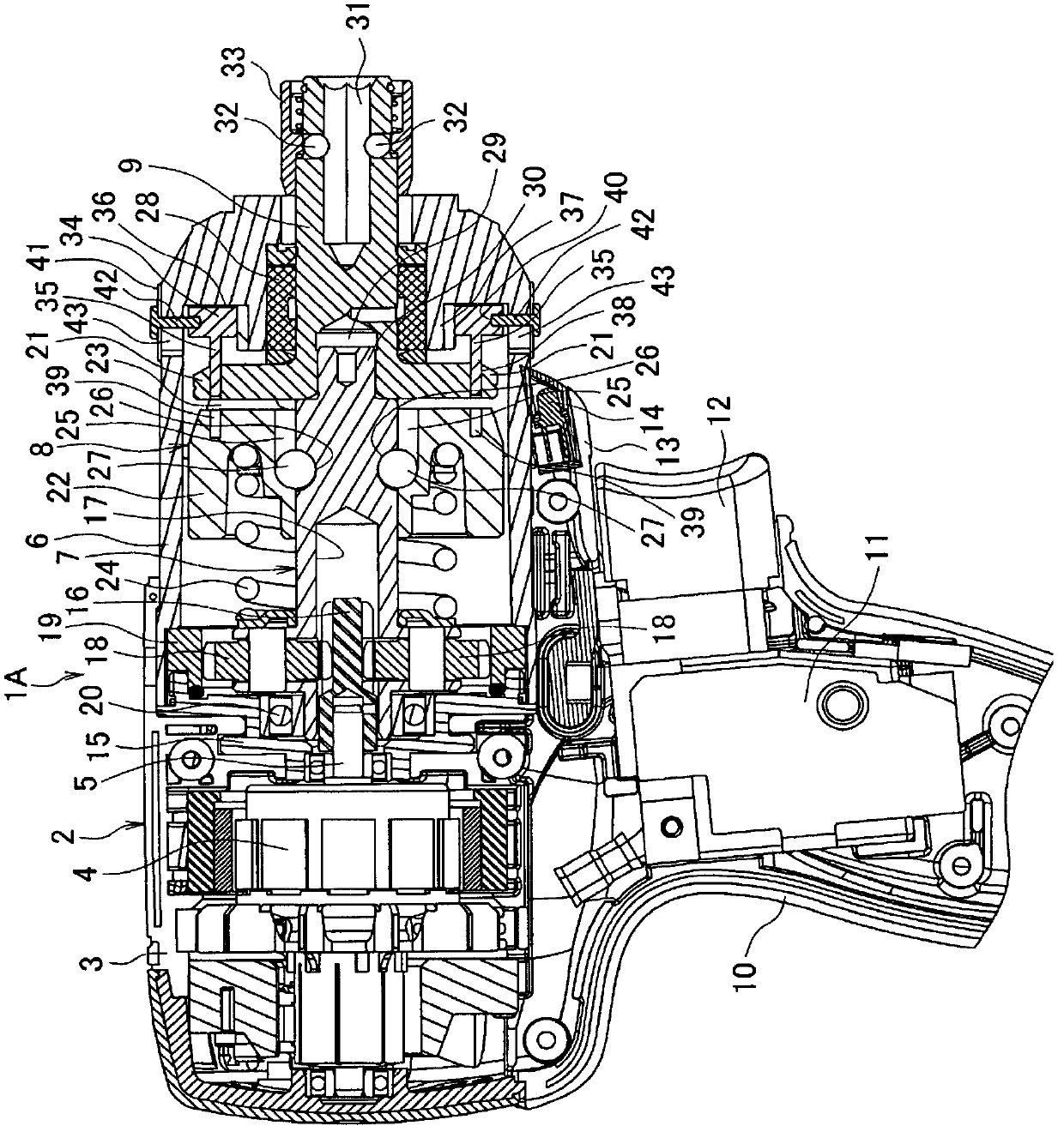
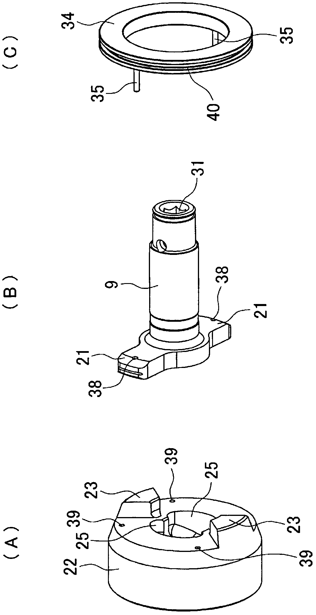
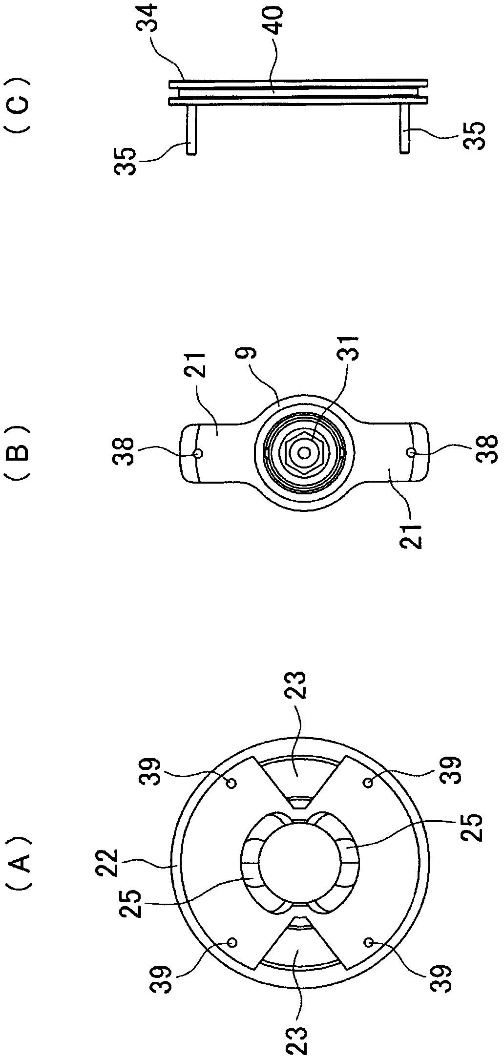
[0046] Such as figure 1 As shown, an impact screwdriver 1A as an example of an impact tool has: a main body case 2, which is formed by assembling left and right half cases 3, 3, and houses a motor 4; and a hammer case 6 with a bell-shaped cross section. , which is the front shell, assembled in front of the main body shell 2 ( figure 1 The right side in the middle), and accommodate the main shaft 7, the impact mechanism 8, and the anvil 9. A handle 10 is extended below the main body case 2 , and a switch 11 with a trigger 12 is housed in the upper portion of the handle 10 . A battery pack (not shown) serving as a power source is installed at the lower end of the handle 10 . Further, in th...
PUM
 Abstract
Description
Claims
Application Information