Check patentability & draft patents in minutes with Patsnap Eureka AI!

Illumination device

A technology for lighting devices and metal substrates, which is applied in the direction of lighting devices, lighting auxiliary devices, lighting device components, etc., can solve the problems of high manufacturing costs, reduced durability, and low heat dissipation of flexible printed circuit boards, and achieve Cost reduction of lighting equipment, effect of cost reduction

Active Publication Date: 2012-08-01
KOITO MFG CO LTD
View PDF6 Cites 2 Cited by
  • Summary
  • Abstract
  • Description
  • Claims
  • Application Information

AI Technical Summary

Problems solved by technology

However, there is a problem in that the manufacturing cost of the flexible printed circuit board becomes high when the joint base portion, the excess portion, and the card end connector are formed by separate components.
[0005] On the other hand, in Patent Document 1, which is an LED mounting board, the base part is generally formed of resin, so the heat dissipation is low.
Substrates with low heat dissipation have problems in reducing the durability of LEDs due to heat remaining in the mounted LEDs. Therefore, higher heat dissipation is required for LED mounting substrates

Method used


Image

  • Illumination device
  • Illumination device
  • Illumination device

Examples


Embodiment Construction

[0051] Embodiments of the present invention will be described below with reference to the drawings. In the following embodiments, various limitations are made on constituent elements, types, combinations, shapes, relative arrangements, etc., but these are merely examples, and the present invention is not limited thereto.

[0052] First, refer to figure 1 with figure 2 A first embodiment of the lighting device of the present invention will be described.

[0053] exist figure 1 , represents the lighting device of this embodiment. figure 1 The illuminating device 1 is used for a vehicle lamp, and is composed of a metal base FPC 5 , a light emitting element (LED) 6 , and a lighting control circuit 7 .

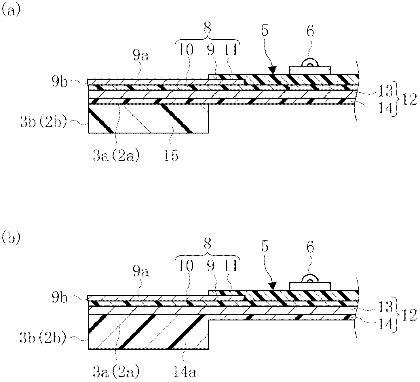
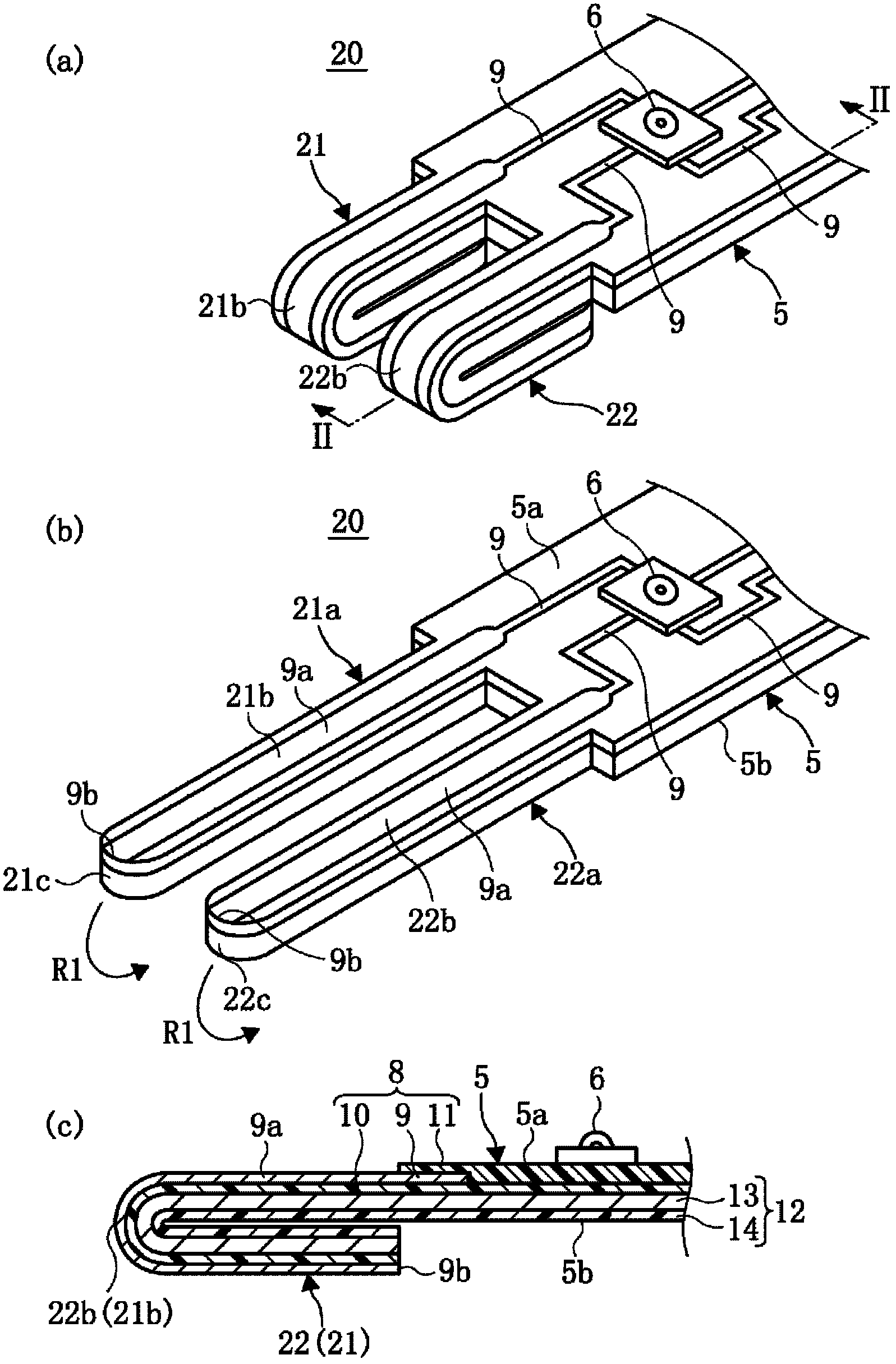
[0054] In addition, a pair of terminal parts 2 and 3 are provided on the metal base FPC5. The terminal portions 2 and 3 are parallel convex portions protruding along the surface 5a of the metal base FPC5, and are integrally formed by processing the end of the metal base FPC5....


PUM


Abstract

An illumination device including a light emitting element (6) and a lighting control circuit (7) on a metal base flexible printed circuit board (FPC) 5) that is formed by integrating a flexible metal base (12) with a flexible printed circuit board (8) which is formed by integrating a copper foil pattern (conductive body) (9) with films (10,11), wherein end portions of the metal base FPC (5) are formed as thick terminal portions (21,22). An illumination device characterized by low manufacture cost and light emitting element with durability difficult to reduce.

Description

technical field [0001] The present invention is an invention of a lighting device that is low in production cost and hardly degrades the durability of a light emitting element. Background technique [0002] Patent Document 1 shows a lighting device using LEDs. The lighting device of Patent Document 1 is formed by accommodating a flexible printed circuit board on which LEDs are mounted inside a housing body having a rectangular cylindrical connector housing portion and attaching a cover. The flexible printed circuit board is composed of a base body on which LEDs, resistors, and diodes are installed, a flexible excess length portion provided on the base portion, and a card edge connector disposed at the front end of the excess length portion. The card end connector functions as a connector terminal by arranging and fixing the excess length portion at a predetermined position of the connector housing portion while the base portion is fixed in the housing body. [0003] [Paten...

Claims


Application Information

Patent Timeline
Patent Type & Authority Applications(China)
IPC IPC(8): F21S2/00F21V21/00F21W107/10
CPCF21S48/215F21S48/212F21V23/06H05K2201/2009F21K9/13H05K2201/10106H05K1/118H05K2201/055F21Y2101/02H05K1/189H05K1/028F21K9/23F21Y2115/10F21S43/195F21S43/14
Inventor 大坪高之松永崇伊东范明
Owner KOITO MFG CO LTD
Features
  • R&D
  • Intellectual Property
  • Life Sciences
  • Materials
  • Tech Scout
  • Unparalleled Data Quality
  • Higher Quality Content
  • 60% Fewer Hallucinations
Learn More