Method and computer system for scattered beam correction in a multi-source CT

A computer program, corrected technique, applied to instruments used in radiological diagnosis, calculations, material analysis using wave/particle radiation, etc., to solve problems such as confusion errors, inability to scan data, lack of scattered beam profiles, etc., to achieve flexible modeling, avoiding the effect of ambiguity

Inactive Publication Date: 2012-08-29
SIEMENS HEALTHCARE GMBH
View PDF6 Cites 9 Cited by
  • Summary
  • Abstract
  • Description
  • Claims
  • Application Information

AI Technical Summary

Problems solved by technology

This leads to a gradual loss of agreement between the measured scattered beam profile and the necessary data corrections as the z-coverage of the detector increases
[0010] A third method (iii) that alternately blanks the corresponding raw radiance and directly measures the lateral scatter during the blanking phase (iii) While there may be no lack of agreement in the data in the z d

Method used


Image

  • Method and computer system for scattered beam correction in a multi-source CT
  • Method and computer system for scattered beam correction in a multi-source CT
  • Method and computer system for scattered beam correction in a multi-source CT

Examples


Embodiment Construction

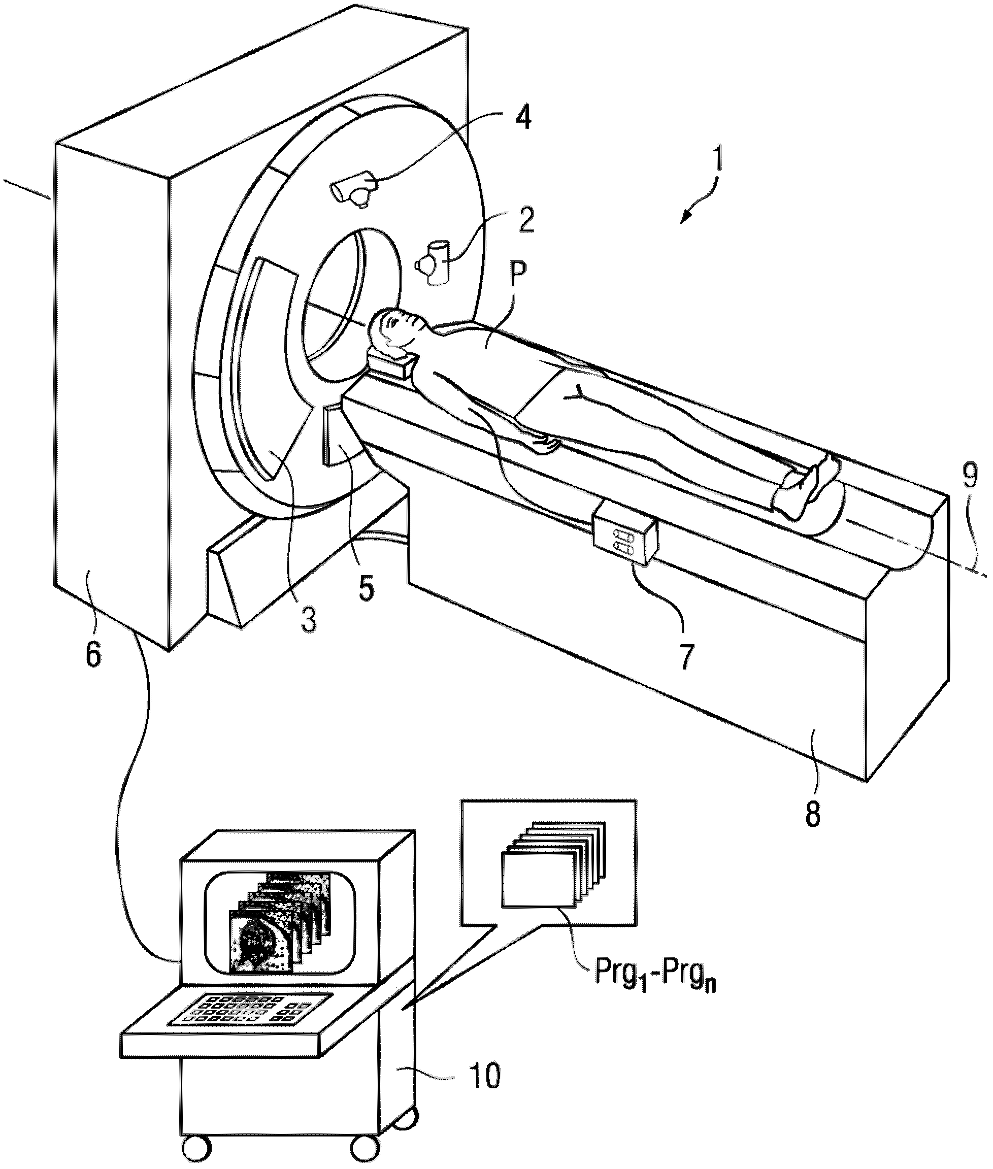
[0074] figure 1 The drawing shows an example of a dual-source CT system (=CT system with two radiator-detector systems) 1 with a gantry housing 6, in which two A radiator-detector system arranged in an angularly staggered manner. The radiator-detector system consists of a first X-ray tube 2 and a detector 3 corresponding to the first X-ray tube on the one hand, and on the other hand consists of a second X-ray tube 4 and a detector corresponding to the second X-ray tube. The ray tube is composed of detectors 5 arranged opposite to each other. Both emitter-detector systems sweep the measuring field arranged in the central circular opening. The patient P can be moved along the system axis 9 through the measurement field by means of the patient couch 8 . In principle, both helical and sequential scans are thus performed. A contrast medium can also be injected into the patient via the contrast medium applicator 7 in order to improve the imaging of blood vessels or other structu...


PUM


Abstract

A method and a computer system (10) are disclosed for scattered beam correction in a CT examination of an object in a multi source CT. In at least one embodiment, the method includes generating original projection data records; reconstruction of the object (P) with the original projection data records of at least one detector (3,5); determining the scattered radiation generated by each emitter (2,4) exclusively in the direction of the original beams of the at least one other emitter relative to its opposing detector (3,5); generating corrected projection data records by removing the calculated scattered radiation from the original projection data records; reconstruction of the object (P) with the corrected projection data records, and implementing a further iteration of the method when determining the scattered radiation or issuing the reconstruction result if at least one predetermined abort criterion applies.

Description

technical field [0001] The invention relates to a method and a computer system for scattered beam correction during a CT examination of an object in multi-source CT, wherein the scattered beam correction is carried out iteratively on projection data. Background technique [0002] In dual-source CT, by using two radiator-detector systems simultaneously, the x-ray quanta are scattered at the object to be measured from the x-ray radiator of the first radiator-detector system to an angularly offset ground on the same gantry The detectors of the second radiator-detector system are arranged, and vice versa. These so-called lateral scatter must be corrected by suitable methods in order to avoid artifacts. For this, it is necessary to identify the profile of the scattered beam intensity in each projection. [0003] The following three methods are basically known for this purpose: [0004] (i) Model-based estimation of the scatter from the sinogram data on the basis of the tempora...

Claims


Application Information

Patent Timeline
IPC IPC(8): A61B6/03
CPCA61B6/032A61B6/06A61B6/4014A61B6/5205A61B6/5282G01N23/046A61B6/4291G06T11/005G06T2211/424G01N2223/419G01N2223/612
Inventor T.弗洛尔M.彼得希尔卡K.斯蒂尔斯托佛
Owner SIEMENS HEALTHCARE GMBH
Why Eureka
Try Eureka