Minimally invasive sighting device

A sighter and base technology, applied in the field of minimally invasive sighters, can solve the problem of large wounds in patients, and achieve the effects of convenient operation, pain relief and simple structure

Active Publication Date: 2014-04-16
SUZHOU KANGLI ORTHOPEDICS INSTR +1
View PDF6 Cites 0 Cited by
  • Summary
  • Abstract
  • Description
  • Claims
  • Application Information

AI Technical Summary

Problems solved by technology

In the prior art, when installing the horizontal connecting rod, the doctor usually needs to open a large opening in the lesion, and then install the horizontal connecting rod on the connecting rod through the opening. The disadvantages of this horizontal connecting rod installation method are: Greater trauma to the patient

Method used


Image

  • Minimally invasive sighting device
  • Minimally invasive sighting device
  • Minimally invasive sighting device

Examples


Embodiment Construction

[0013] The preferred embodiments of the present invention will be described below in conjunction with the accompanying drawings. It should be understood that the preferred embodiments described here are only used to illustrate and explain the present invention, and are not intended to limit the present invention.

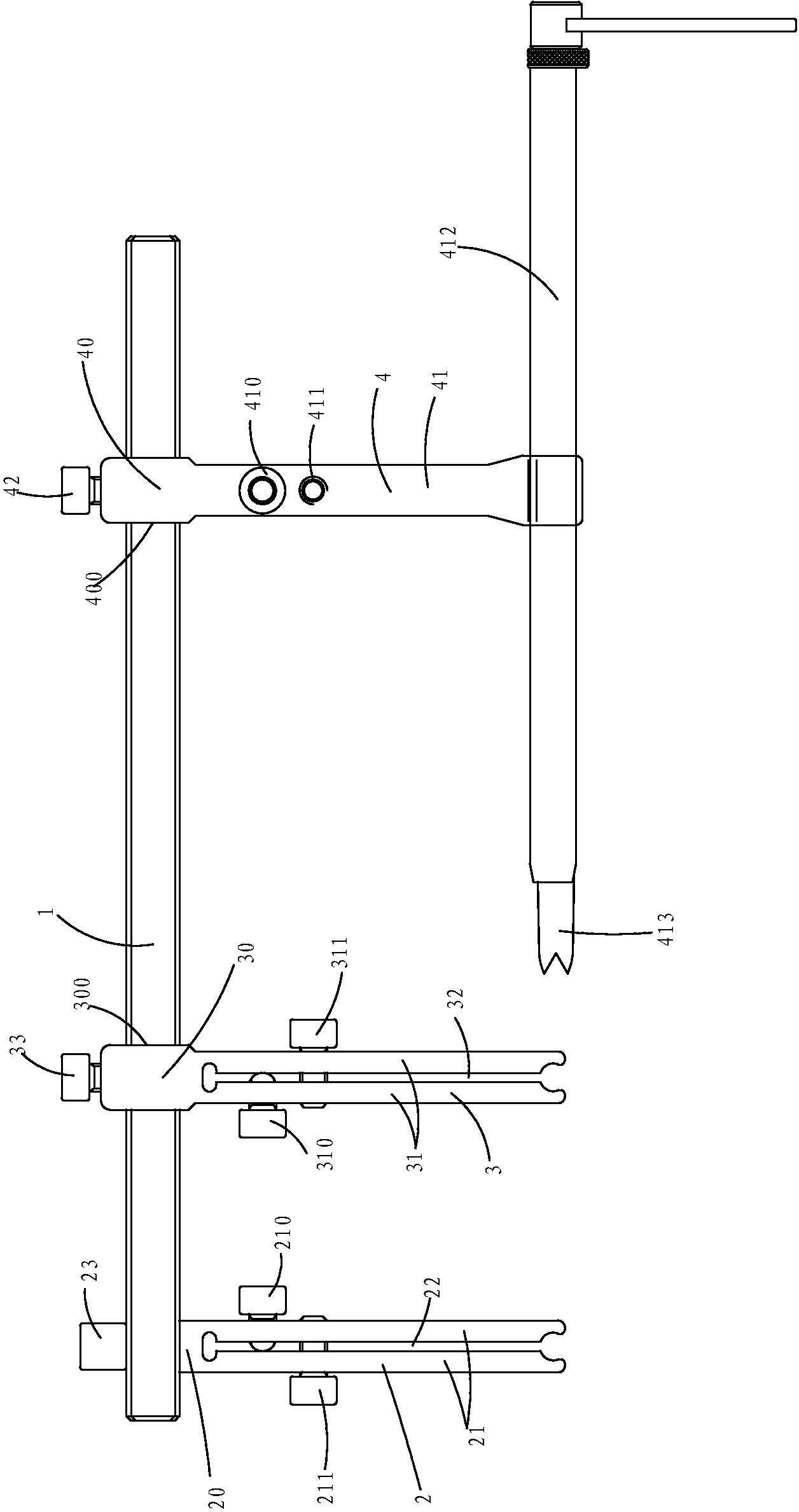
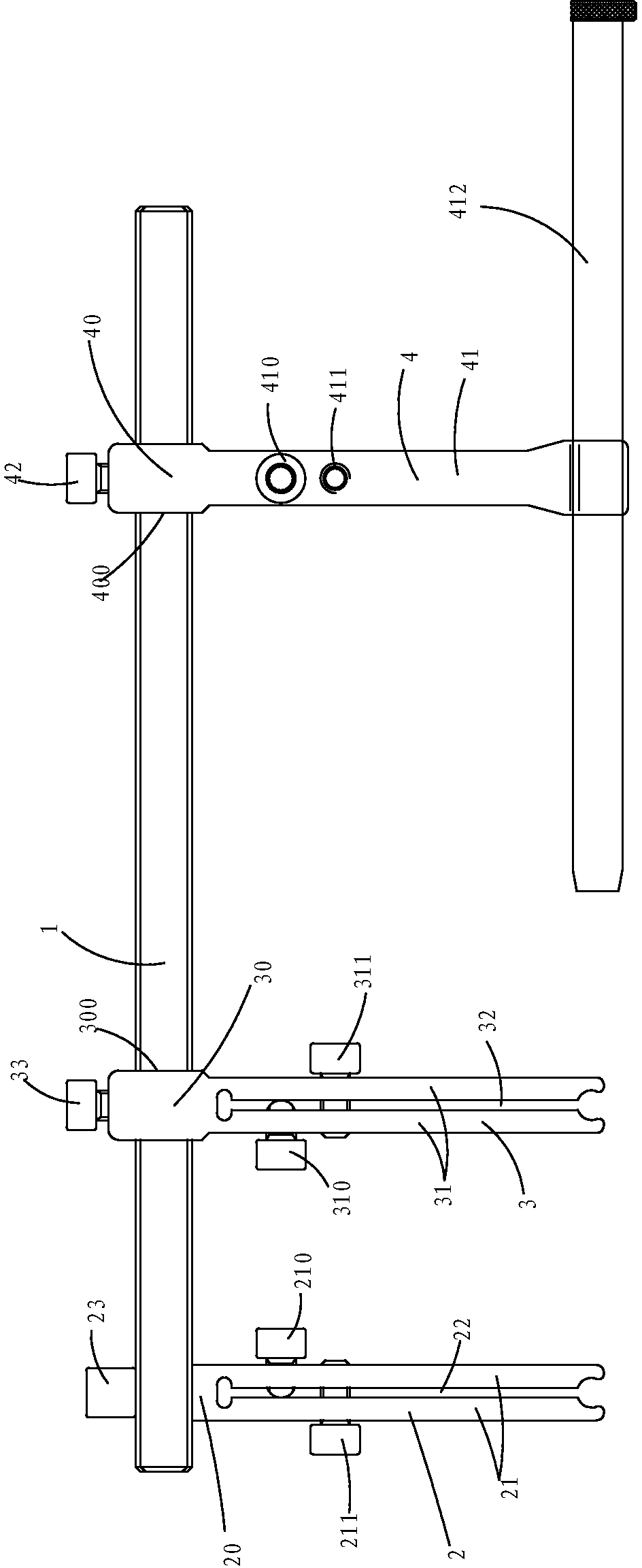
[0014] see Figure 1 to Figure 3 , a minimally invasive collimator, comprising: a beam 1, a first clamping device 2 mounted on one end of the beam 1, a second clamping device 3 and a third clamp which are sleeved on the beam 1 and can slide relative to the beam 1 The clamping device 4, the first clamping device 2 includes a first base 20 and two first clamping arms 21 protruding from the first base 20, a first gap 22 is formed between the two first clamping arms 21 , the first base 20 and the beam 1 are fixed by the first bolt 23, the first clamping arm 21 is installed with the first adjusting bolt 210 and the first locking bolt 211, the first adjusting bolt 210 Th...


PUM


Abstract

The invention discloses a minimally invasive sighting device, which comprises a crossbeam, a first clamping device, a second clamping device and a third clamping device, wherein the first clamping device comprises a first base and two first clamping arms; a first adjusting bolt and a first locking bolt are arranged on each first clamping arm; the second clamping device comprises a second base and two second clamping arms; a second adjusting bolt and a second locking bolt are arranged on each second clamping arm; the third clamping device comprises a third base and two third clamping arms; a third adjusting bolt and a third locking bolt are arranged on each third clamping arm; a sleeve is clamped between the two third clamping arms; a first through hole is formed on the second base; a second through hole is formed on the third base; and the crossbeam penetrates through the first through hole and the second through hole. The minimally invasive sighting device is simple in structure, convenient to operate and low in cost.

Description

technical field [0001] The invention relates to a medical device, in particular to a minimally invasive collimator. Background technique [0002] Modern people often suffer from spinal injuries or degenerative lesions due to years of poor sitting or sleeping postures, wrong exercise methods, or other accidents. In order to improve the impact of spinal deformation on patients' work and rest, It is necessary to adjust and fix the traumatized or diseased vertebrae through surgery, and then cooperate with subsequent correction and rehabilitation work, so that the entire or partial vertebral structure can return to normal. Under the premise of considering ergonomics and structural strength, an appropriate spinal fixator can be designed and implanted into the injured or diseased vertebral body, and the appropriate span and angle can be adjusted according to the condition of the patient's spine, so that The entire fixer is integrated with the vertebral body to achieve a complete f...

Claims


Application Information

Patent Timeline
Patent Type & Authority Patents(China)
IPC IPC(8): A61B17/90
Inventor 陈国平陆军曹刚
Owner SUZHOU KANGLI ORTHOPEDICS INSTR
Why Eureka
Try Eureka