A pile frame lifting operation mechanism

A technology of operating mechanism and pile frame, which is applied in the direction of lifting device, etc., can solve the problems of safety hazards for maintenance personnel, location on the side of the column, unfavorable fault detection and elimination, etc., to achieve convenient and reliable operation, improve the operating range, and improve safe operation performance Effect

Active Publication Date: 2015-12-09
上海工程机械厂有限公司
View PDF7 Cites 0 Cited by
  • Summary
  • Abstract
  • Description
  • Claims
  • Application Information

AI Technical Summary

Problems solved by technology

If the height of the pile frame column is low, or the operating device is in the middle and lower part of the column, the maintenance personnel can use the ladders on both sides of the column to climb up the column and approach the operating device. Since the maintenance personnel climb the ladder on the side of the column with bare hands, it is impossible to carry a large Large and heavy inspection tools and replacement parts, and the ladder is located on the side of the column, so it is impossible to correctly understand the situation of the working device located on the guide rail on the front of the column; Elevate the maintenance personnel to a high altitude close to the operating device on the column, but the hanging cage will sway and shake under the influence of wind force at high altitude, and may collide with the column and the operating device, which will bring greater safety hazards to the maintenance personnel and is not conducive to failure detection and exclusion

Method used


Image

  • A pile frame lifting operation mechanism
  • A pile frame lifting operation mechanism
  • A pile frame lifting operation mechanism

Examples


Embodiment Construction

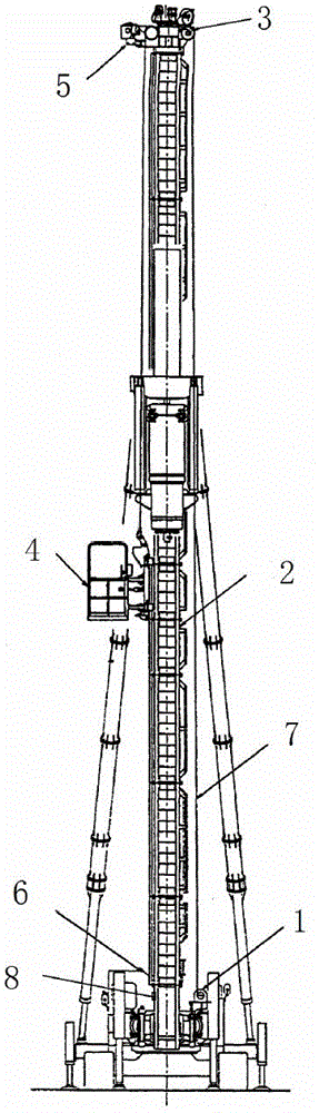
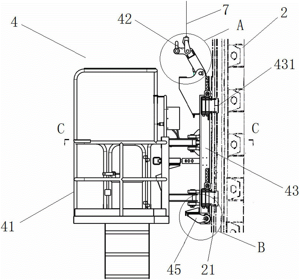
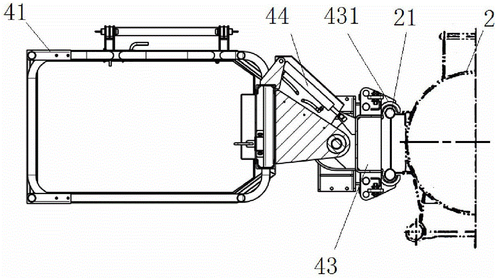
[0020] like Figure 1 to Figure 8 As shown, a pile frame lifting operation mechanism includes a hoist unit 1 with a hydraulic motor on the frame chassis platform, a column 2, a top pulley frame 3, a working cage 4, a hoist over-roll limiter 5, and a hoist over-release Limiter 6, steel wire rope 7, stop block 8 and speed regulation control system 9, wherein, operation cage 4 comprises cage body 41, hoist frame 42, frame 43 and rotary oil cylinder 44; It is characterized in that: described column 2 is provided with a pair of side guide rails 21 arranged symmetrically along its axial direction and ribs 22 arranged equidistantly between the pair of guide rails; the top pulley frame 3 is fixed on the top of the column 2 through bolts and nuts; The frame 43 is symmetrically arranged with a guide plate 431, and the operation cage 4 is placed on the side guide rail 21 of the column 2 through the guide plate 431 of the frame 43; the cage body 41 is hingedly connected with the frame 43 ...


PUM


Abstract

The invention discloses a pile frame lifting operation mechanism which comprises a hoisting machine group, a vertical column, a top pulley yoke, an operating suspension cage, a hoisting machine over-hoisting limiter, a hoisting machine over-releasing limiter, a wire rope, stop dogs and a speed control system. The vertical column is provided with a pair of side guide rails and rib plates distributed at equal intervals; the operating suspension cage is arranged on the side guide rails; a suspension cage body is hinged with a frame; an angling cylinder is respectively connected with the suspension cage body and the frame; the hoisting machine over-hoisting limiter and the hoisting machine over-releasing limiter are respectively installed in proper positions of lower parts of the top pulley yoke and the vertical column; the wire rope is connected with a hoisting frame; the hoisting frame adopts a rod piece, is installed at the upper part of the frame through a hinge pin and can rotate around the hinge pin; a spring connected with the frame is arranged at the lower end part of the hoisting frame; a throttle valve is arranged in the speed control system; and the stop dogs are symmetrically distributed in proper positions at lower parts of the side guide rails. The pile frame lifting operation mechanism ensures that the operating suspension cage is lifted and rotates along the side guide rails of the vertical column, is convenient to operate, stable and reliable, is convenient to mount and dismount, and guarantees the safety of operating personnel.

Description

technical field [0001] The invention relates to a lifting operation mechanism, in particular to a pile frame lifting operation mechanism. Background technique [0002] In modern pile foundation construction, the pile frame is generally used as the working machine, and various construction equipment such as multi-axis drilling machines, long auger drilling machines, vibratory hammers, diesel hammers and hydraulic hammers are installed on the columns to carry out underground construction. Pile foundation engineering construction can meet various pile foundation construction needs such as underground diaphragm wall, on-site mixing pile, compacted sand pile and prefabricated pile. In recent years, as the depth of underground pile foundations has become higher and higher, the height of the pillars of the pile frame has also continued to increase, generally above 30 meters. At present, the maximum height of the pillars of the largest walking pile frame in China has reached 60 mete...

Claims


Application Information

Patent Timeline
Patent Type & Authority Patents(China)
IPC IPC(8): B66F11/04
Inventor 毛雪峰毛维耀张国柱
Owner 上海工程机械厂有限公司
Why Eureka
Try Eureka