Switching mechanism and interlocking device thereof

A technology of a switch mechanism and an interlocking device, which is applied in the field of the switch mechanism and the interlocking device of the switch mechanism, can solve the problems of mutual influence, complex movement trajectory of the interlocking device, and damage to the operator's switch mechanism.

Inactive Publication Date: 2013-03-27
SIEMENS AG
View PDF4 Cites 5 Cited by
  • Summary
  • Abstract
  • Description
  • Claims
  • Application Information

AI Technical Summary

Problems solved by technology

In another case, when the operator opens the front cover for maintenance after the switch mechanism is opened, the switch mechanism may be closed by misoperation, which may also cause the operator to get an electric shock and damage the switch mechanism.
[0003] In order to avoid the above dangers, interlocking devices are usually installed in the switch mechanism, so that when the switch mechanism is in the disconnected state, the switch mechanism cannot be closed after the front cover is removed; when the switch mechanism is in the closed state, the front cover cannot be removed
However, the movement trajectory of the existing interlocking device is complex, and the various parts of the interlocking device may affect each other during the movement, thus affecting the reliability and durability of the interlocking device

Method used


Image

  • Switching mechanism and interlocking device thereof
  • Switching mechanism and interlocking device thereof
  • Switching mechanism and interlocking device thereof

Examples


Embodiment Construction

[0049] In order to have a clearer understanding of the technical features, purposes and effects of the invention, the specific embodiments of the present invention are now described with reference to the accompanying drawings, in which the same symbols represent the same parts or parts with similar structures but the same functions.

[0050] In order to keep the drawings concise, the parts related to the content of the invention are only schematically shown in each drawing, and they do not represent the actual structure of the product. In addition, to make the drawings concise and easy to understand, in some drawings, only one of the components having the same structure or function is schematically shown, or only one of them is marked.

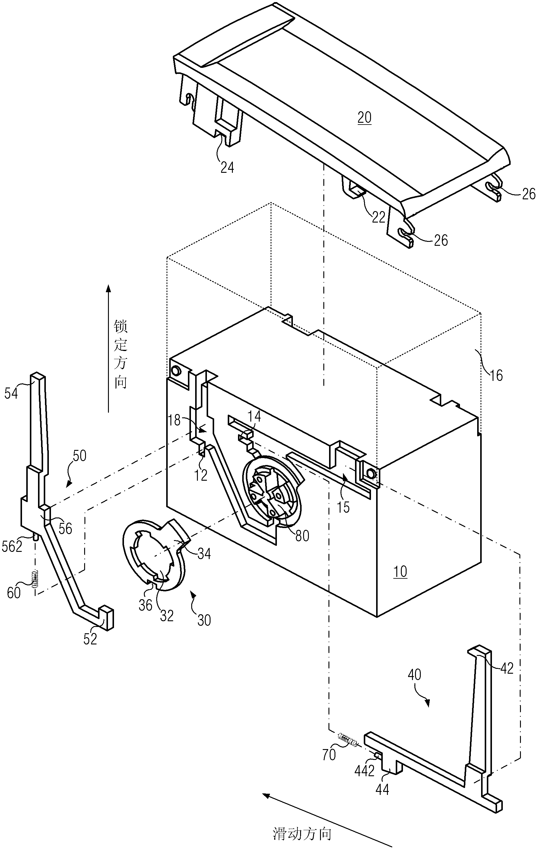
[0051] Herein, "above" is only used to indicate the relative positional relationship between the end cap 20 and the support body 10 , rather than to limit their absolute position.

[0052] figure 1 It is a three-dimensional exploded schematic...


PUM


Abstract

The invention provides an interlocking device of a switching mechanism. The interlocking device comprises a support (10), an annular part (30), a first locking rod (50), a first elastic part (60), a second locking rod (40), an end cover (20) and a second elastic part (70). A clamping portion can be connected with limiting parts so as to limit the annular part during rotation. The first elastic part can push the first locking rod to slide along a locking direction in which the clamping portion is clamped with the limiting parts. A locking portion can be fastened on the end cover, and a contact portion is abutted onto the end cover and further can push the clamping portion to slide along a direction opposite to the locking direction. The second elastic part can push the second locking rod to slide along a direction opposite to a sliding direction in which the locking portion can be clamped on the end cover. The pushing part can push a second driving portion to slide along the sliding direction, so that the locking portion is clamped with the end cover. The interlocking device of the switching mechanism has the advantages that the movement stability and the movement reliability of each locking rod are improved, and the durability of the interlocking device is enhanced. The invention further provides the switching mechanism comprising the interlocking device.

Description

technical field [0001] The present invention relates to an interlocking device for a switch mechanism, in particular to an interlocking device for locking a switch mechanism that cannot open an end cover in a closed state, and that cannot be closed when the switch mechanism is disconnected and the front cover is opened. A switch mechanism using the interlock is also provided. Background technique [0002] During the use of the switch mechanism, it is often necessary to open the front cover to replace the fuse or check the internal conditions of the switch mechanism. In consideration of safety, it is necessary to open the switch mechanism first, and then open the front cover. However, due to no protective measures, the operator may accidentally open the front cover before the switch mechanism is opened, causing electric shock to the operator and switching off. Institutional damage. In another case, when the operator opens the front cover for maintenance after the switch mec...

Claims


Application Information

Patent Timeline
Patent Type & Authority Applications(China)
IPC IPC(8): H01H9/22H01H85/25
Inventor 刘云李翔姜晓军吕远段新高王砚波黄静姜禹宋建康
Owner SIEMENS AG
Why Eureka
Try Eureka