
Glass knife
A technology of glass knife and knife bar, which is applied in glass manufacturing equipment, glass cutting devices, manufacturing tools, etc., can solve problems such as troublesome operation and deviation of parallel lines, and achieve the effects of convenient operation, small frictional resistance, and accurate parallelism
- Summary
- Abstract
- Description
- Claims
- Application Information
AI Technical Summary
Problems solved by technology
Method used
Image

Examples
Embodiment Construction
[0029] The present invention will be described in further detail below in conjunction with the accompanying drawings and specific embodiments.
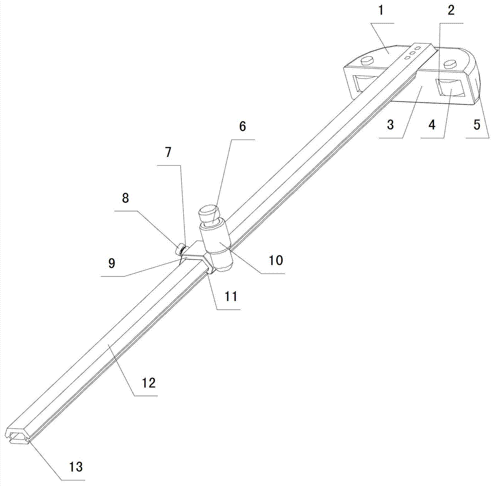
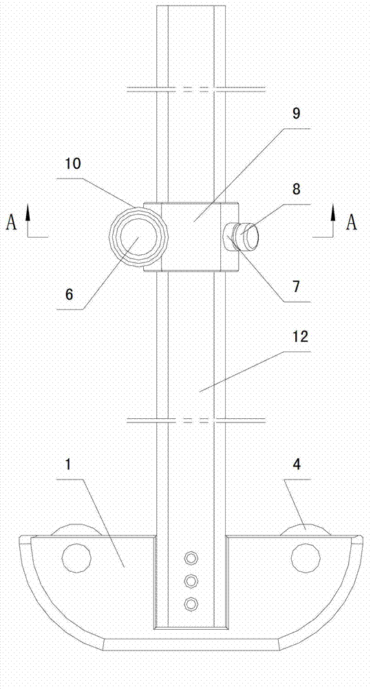
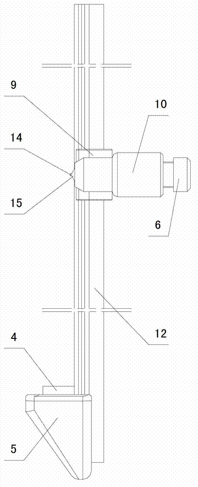
[0030] Depend on Figure 1 to Figure 7 As can be seen from the shown structural representation of the glass cutter of the present invention, it comprises a cutter head 14 and a knife bar 15, and said cutter head 14 is arranged at one end of the knife bar 15, and it also includes a backing plate, a ruler 12 and a sliding device, so One end vertical direction of said ruler 12 is fixedly connected on the backing plate, and the slide device is slidably connected with the ruler 12, and the cutter bar 15 is connected with the slide device and is perpendicular to the plane of the ruler 12 close to the glass surface.
[0031] The backing plate is formed by connecting the upper panel 1, the lower panel 16, the vertical panel 3 and the side panel 5, one end of the ruler 12 is fixedly connected to the upper panel 1, and the vertical panel 3 has ...
PUM
 Abstract
Description
Claims
Application Information