A signal transmission method and device

A signal transmission and signal technology, applied in the field of signal transmission, can solve the problems of base station transmission power loss, performance gain cannot make up for subcarrier signal performance loss, etc., and achieve the effect of small power fluctuation

Active Publication Date: 2016-01-20
HUAWEI TECH CO LTD
View PDF4 Cites 0 Cited by
  • Summary
  • Abstract
  • Description
  • Claims
  • Application Information

AI Technical Summary

Problems solved by technology

The implementation of the wide beam is to multiply each subcarrier of each physical antenna by a weighting factor with the same phase before transmitting the signal. In order to achieve the weighted beam shape that meets the coverage requirements of the cell, some physical antennas correspond to the transmission The channel must be transmitted with reduced power, resulting in a loss of base station transmission power; the CDD implementation method is to multiply each subcarrier of each physical antenna by a weighting factor with a different phase before transmitting the signal. The performance gain brought by this implementation method may not be sufficient Make up for the performance loss caused by subcarrier signal fluctuations

Method used


Image

  • A signal transmission method and device
  • A signal transmission method and device
  • A signal transmission method and device

Examples


Embodiment 1

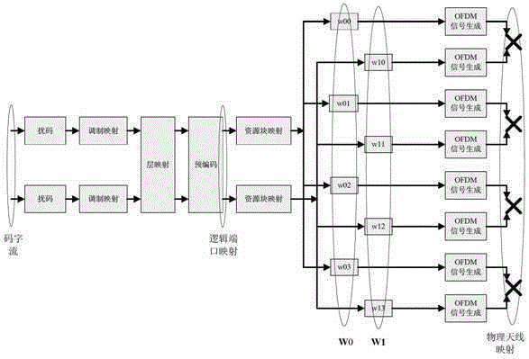
[0027] This embodiment provides a signal transmission method, and the method is applied to a communication system including 2 logical ports and 8 physical antennas, the 2 logical ports are logical ports 0 and 1, and the 8 physical antennas are physical antennas 0, 1, 2, 3 and physical antennas 4, 5, 6, 7;

[0028] The antennas referred to in the present invention all refer to physical antennas, and the 8 physical antennas can be co-polarized antennas or cross-polarized antennas. In this embodiment, 4 columns are corrected to the array elements, equally spaced, and each column is positive 45 degrees Take a negative 45-degree cross-polarized physical antenna as an example for illustration.

[0029] figure 2 is an implementation structure adopted by the signal transmission method, such as figure 2 As shown, the two Port signals that have been precoded (Precoding) are mapped to 8 physical antennas after weighted processing. The mapping method can be to map the signal of logica...

Embodiment 2

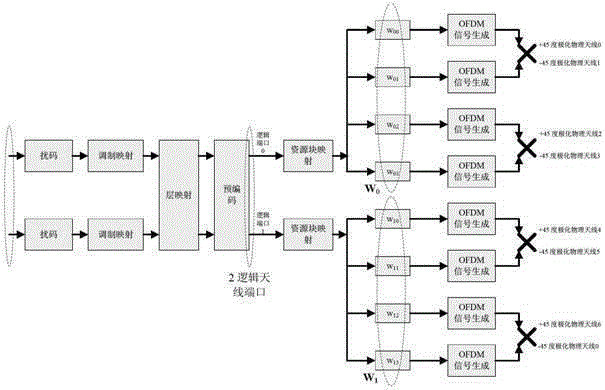
[0049] This embodiment provides a signal transmitting device, which is connected to the communication system or located in the communication system, the communication system includes 2 logical ports and 8 physical antennas, the 2 logical ports are logical ports 0 and 1, The eight physical antennas are physical antennas 0, 1, 2, and 3 and physical antennas 4, 5, 6, and 7;

[0050] The antennas referred to in the present invention all refer to physical antennas, and the 8 physical antennas can be co-polarized antennas or cross-polarized antennas. In this embodiment, 4 columns are corrected to the array elements, equally spaced, and each column is positive 45 degrees Take a negative 45-degree cross-polarized physical antenna as an example for illustration.

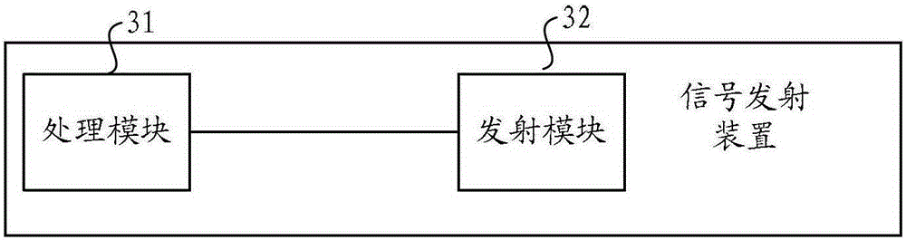
[0051] image 3 is a structural schematic diagram of the signal transmitting device, in which logical ports and physical antennas are omitted, such as image 3 As shown, the signal transmitting device includes:

[0052] Th...

Embodiment 3

[0072] This embodiment provides a signal transmitting device located in a communication system including 2 logical ports and 8 physical antennas, Figure 4 is a structural schematic diagram of the signal transmitting device, such as Figure 4 shown, including:

[0073] Memory 41, used to store process codes;

[0074] The processor 42 is configured to execute the signal weighted mapping method described in Embodiment 1 according to the process code stored in the memory 41;

[0075] The transmitter 43 is configured to transmit the signal weighted and mapped by the processor 42 .


PUM


Abstract

Provided is a signal transmission method. By multiplying each sub-carrier of 8 physical antennae by a weighting factor of a specific phase, and making the phase of the weighting factor of any one of the physical antennae 0, 1, 2, and 3 and any one of the physical antennae 4, 5, 6, and 7 have one more π, and then transmitting signals, the signal transmission method cannot result in the loss of base station transmission power, the power fluctuation amplitude of the sub-carrier is also relatively small, and especially when a malfunction occurs on one path of an antenna, the performance loss cannot be too large.

Description

technical field [0001] The present invention relates to the communication field, in particular to a signal transmission method in the communication field. Background technique [0002] With the increasingly higher requirements for the throughput and coverage performance of wireless communication systems, multiple-input multiple-output (Multi-input Multi-output, referred to as "MIMO") technology and orthogonal frequency division multiplexing (Orthogonal frequency division multiple, referred to as " The combination of OFDM") technologies has become a hotspot, such as the Long Term Evolution (Long Term Evolution, referred to as "LTE") system. In the application of MIMO technology, the number of logical data channels and physical data channels may not be equivalent, and a corresponding relationship between the two needs to be established, that is, logical data channels (or logical ports) are mapped to physical data channels (or physical antenna ports). The current commercial LT...

Claims


Application Information

Patent Timeline
Patent Type & Authority Patents(China)
IPC IPC(8): H04B7/06H04L1/06
CPCH04B7/0465H04W52/143
Inventor 黄晖黄建波
Owner HUAWEI TECH CO LTD
Why Eureka
Try Eureka