Transmission structure of spiral spreading machine distributor

A technology of screw distributor and transmission structure, which is applied to roads, road repair, roads, etc., can solve the problems of inflexible loading and unloading, inconvenient production and maintenance, and poor anti-segregation effect, and achieves stable and reliable transmission effect. Simple structure and low assembly process requirements

Inactive Publication Date: 2013-04-24
CHENGDU XINZHU CONCRETE MASCH EQUIP CO LTD
View PDF6 Cites 1 Cited by
  • Summary
  • Abstract
  • Description
  • Claims
  • Application Information

AI Technical Summary

Problems solved by technology

[0003] The power transmission device of the distributor is from the driven tooth to the screw shaft body. In the traditional way, one adopts the jaw-type transmission method. Although the transmission effect is stable, it has high requirements for the production and processing of the jaw shaft, and Due to the use of tooth-embedded assembly, it is not flexible enough for loading and unloading, which may easily cause inconvenience in production and maintenance.
Another transmission method is the method of "locating the positioning shaft and driving the screw shaft by the bolt cap". This method is convenient for the installation of the screw shaft on the construction site, but it generally does not have reverse blades, so the anti-segregation effect of the middle part of the road surface during construction is not good. very good

Method used


Image

  • Transmission structure of spiral spreading machine distributor
  • Transmission structure of spiral spreading machine distributor

Examples


Embodiment Construction

[0023] The present invention will be further described below in combination with specific embodiments and accompanying drawings.

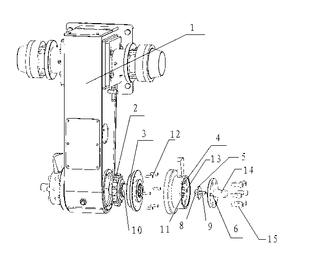
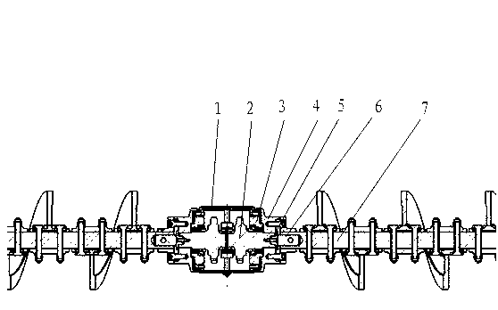
[0024] As shown in the figure, a transmission structure of a paver spiral distributor includes a spiral material distribution box 1, a driving wheel and a driven wheel 2 driven by the driving wheel are arranged inside the spiral material distribution box, and the driven wheel 2 passes through the bearing Installed in the spiral distribution box, the right part of the driven wheel is provided with a bearing end cover 3, a joint 4, an end plate 5, a main shaft fixed body 6, and a screw shaft 7, and the bearing end cover is fixedly connected to the spiral distribution box Above, the left end surface of the bearing end cover presses the driven wheel, and the driven wheel drives the joint to rotate. The end plate is provided with an embedded section 8 embedded in the driven tooth and a limiting section 9 for axially limiting the joint. The main shaft fix...


PUM


Abstract

The invention discloses a transmission structure of a spiral spreading machine spiral distributor. The transmission structure comprises a spiral distribution box, wherein the spiral distribution box is internally provided with a driving wheel and a driven wheel driven by the driving wheel, and the driven wheel is arranged in the spiral distribution box through a bearing; the right part of the driven wheel is sequentially provided with a bearing end cover, a joint, an end plate, a main shaft fixing body and a spiral shaft, and the bearing end cover is fixedly connected on the spiral distribution box; the left end surface of the bearing end cover can press the driven wheel, the driven wheel drives the joint to rotate, and the end plate is provided with an embedding section embedded in driven teeth and a spacing section which can be used for spacing the joint; and the main shaft fixing body can be used for sealing the end plate on the right end of the joint, and the main shaft fixing body is connected with the spiral shaft and can drive the spiral shaft to rotate. The transmission structure provided by the invention has the advantages that the structure is simple, the use is convenient, the manufacturing accuracy on parts and the assembling process requirements on a whole mechanism are lower, the spiral shaft can be located and can be transferred with power through the assembling connection of the main shaft fixing body and the spiral shaft, and the operation reliability of the mechanism is guaranteed.

Description

technical field [0001] The invention relates to a transmission structure of a paver screw distributor. Background technique [0002] The screw distributor is a kind of material distribution device commonly used in road machinery. The screw distributor is installed at the rear of the paver. The power transmission route is: motor-driving gear-chain drive-driven gear-helical shaft. The left and right sides of the screw shaft form independent systems, which can work simultaneously or independently. The paver auger has two functions of mixing and conveying. Whether its structural performance is reasonable will directly affect the production capacity of the auger and the construction quality of the road surface. [0003] The power transmission device of the distributor is from the driven tooth to the screw shaft body. In the traditional way, one adopts the jaw-type transmission method. Although the transmission effect is stable, it has high requirements for the production and pro...

Claims


Application Information

Patent Timeline
Patent Type & Authority Applications(China)
IPC IPC(8): E01C19/12
Inventor 袁美海杨强徐强强
Owner CHENGDU XINZHU CONCRETE MASCH EQUIP CO LTD
Why Eureka
Try Eureka