Novel optical path deflection camera lens

A camera lens and optical path technology, which is applied in optics, optical components, instruments, etc., can solve the problems of large aperture deflection angle on the axis, poor spherical aberration correction of the diaphragm, and difficult camera system, etc., and achieves fewer lenses, simple structure, The effect of shortening the optical length

Active Publication Date: 2013-05-15
SANMING FOCTEK PHOTONICS INC
View PDF7 Cites 1 Cited by
  • Summary
  • Abstract
  • Description
  • Claims
  • Application Information

AI Technical Summary

Problems solved by technology

However, due to the large axial aperture angle borne by the relay lens and the poor correction of the spherical aberration of the diaphragm, this solution is difficult to apply to camera systems with large apertures and high resolution requirements.

Method used


Image

  • Novel optical path deflection camera lens
  • Novel optical path deflection camera lens
  • Novel optical path deflection camera lens

Examples


Embodiment

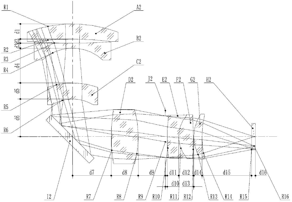
[0062] Table 1 is a kind of embodiment data of optical lens device of the present invention (by focal length f '=1 normalization)

[0063] Initial conditions: object distance l1=-400, image square back intercept l'=2.0108, total optical length TOTR=12.574 object square aperture angle: u1=-0.000775, image square aperture angle: u'=0.298068, maximum F number=F1 .6, maximum viewing angle: 2ω=66.8° (object height 2y=531.9); maximum paraxial image height: 2y'=1.3198; design main spectral line: d, elimination spectral line range: F, C

[0064] In Table 1: n1, n2, n3...n8 are the refractive index of each lens glass material in turn

[0065] v1, v2, v3...v8 are the Abbe coefficients of each lens glass material in turn

[0066] R1, R2, R3...R19 are the curvature radii of each surface of the lens in turn

[0067] d1, d2, d3...d19 are the thickness of each lens or the air space between lenses in turn

[0068] l' is the image square back intercept of the optical system

[0069] Table ...


PUM


Abstract

The invention relates to a novel optical path deflection camera lens which can achieve instant imaging, and also can realize path deflection and meet the requirements on wide angle, large aperture and high-resolution imaging quality. The aims of the invention are achieved by the following technical scheme: the novel optical path deflection camera lens comprises a front group of lenses M, a reflector, a fourth lens and a rear group of lenses N in sequence from an object side to an image side, wherein the fourth lens is a relay lens R with positive focal power for close-range imaging. The novel optical path deflection camera lens has the advantages that by adopting a new scheme of additionally arranging the relay lens with positive focal power for close-range imaging between a front group of wide-angle negative long-range lenses and a rear group of wide-angle negative long-range lenses, the novel optical path deflection camera lens widens an air gap between lenses by using an optical structure with instant imaging, satisfies the space required for optical path deflection, and shortens the optical length along the axial direction.

Description

technical field [0001] The invention relates to a novel optical path deflection camera lens. Background technique [0002] Most of the existing video surveillance systems can be installed in a large space, so there is no need to shorten the total length along the optical axis, so that the matching requirements of large aperture, wide-angle high-definition and long rear working distance can be easily realized, and the structure is also Simple. But in some special occasions (such as limited by the thickness of the installation wall), the camera can only be installed perpendicular to the optical axis or at other angles. Since the focal length of the wide-angle video surveillance camera lens is relatively short, it is difficult to realize the deflection of the optical path by making the back focus very long (for example, the back focus is 4 to 5 times the focal length). The usual solution is to use a wide-angle front objective lens connected to the field lens and the relay len...

Claims


Application Information

Patent Timeline
Patent Type & Authority Applications(China)
IPC IPC(8): G02B13/06G02B13/00G02B17/08G02B1/00
Inventor 林勇杰赖爱光郭少琴张剑表齐海赖英辉
Owner SANMING FOCTEK PHOTONICS INC
Why Eureka
Try Eureka