Maximum power point tracking controller, maximum power point tracking system and maximum power point tracking method

A maximum power point, tracking system technology, applied in control/regulation systems, output power conversion devices, conversion of DC power input to DC power output, etc., can solve problems such as inability to apply energy acquisition, increase circuit complexity and cost, etc.

Active Publication Date: 2013-06-05
IND TECH RES INST
View PDF5 Cites 6 Cited by
  • Summary
  • Abstract
  • Description
  • Claims
  • Application Information

AI Technical Summary

Problems solved by technology

[0003] However, the maximum power point tracking system currently used to collect renewable energy is to detect the current of renewable energy, or to detect current and voltage at the same time to track and calculate the maximum power point, which increases the complexity and cost of the circuit and cannot be applied to energy get on

Method used


Image

  • Maximum power point tracking controller, maximum power point tracking system and maximum power point tracking method
  • Maximum power point tracking controller, maximum power point tracking system and maximum power point tracking method
  • Maximum power point tracking controller, maximum power point tracking system and maximum power point tracking method

Examples


Embodiment Construction

[0060] The following description is of the best mode for carrying out the invention. Those skilled in the art should be able to understand that some modifications, substitutions and substitutions can be made without departing from the spirit and structure of the present invention. The scope of the invention should be determined by the appended claims.

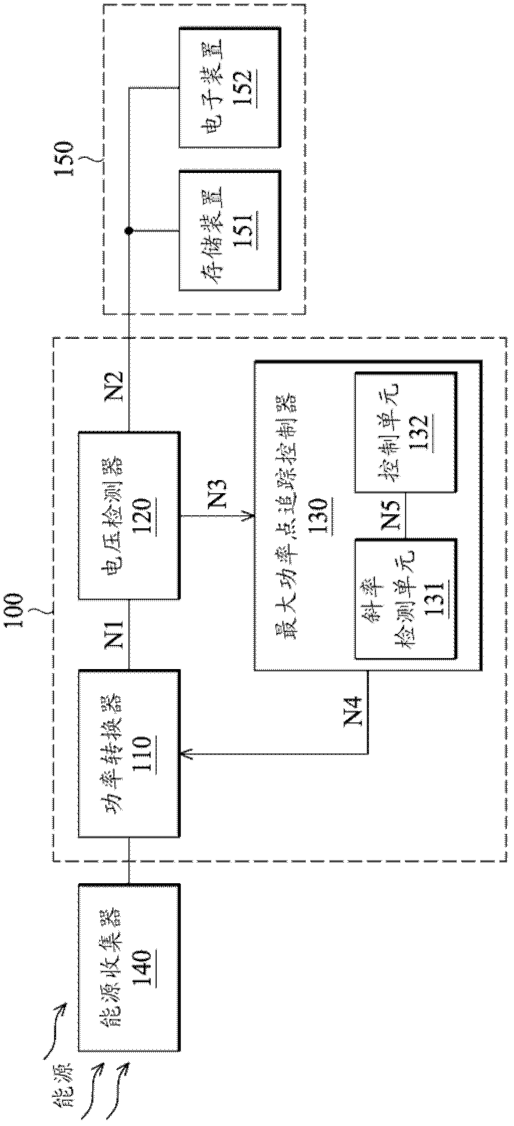
[0061] figure 1 is a schematic diagram of the maximum power point tracking system of the present invention. Such as figure 1 As shown, the maximum power point tracking system 100 includes a power converter 110 , a voltage sensor 120 and a maximum power point tracking controller 130 . The power converter 110 is a DC-DC converter, or an AC-DC rectifier combined with a DC-DC converter, but not limited thereto. In detail, the power converter 110 is used to convert the energy output by an energy harvester (energy harvester) 140 into an output voltage N1 according to a pulse width modulation (PWM) signal N4, so as to drive a load...


PUM


Abstract

The present invention discloses a maximum power point tracking controller, a maximum power point tracking system and a maximum power point tracking method. The maximum power point tracking controller, suitable for controlling an output voltage of a power converter is provided, includes a slope detection unit and a control unit. The slope detection unit calculates whether the output voltage is in a positive trend or in a negative trend according to a detection signal corresponding to the output voltage in order to output a trend signal, in which the voltage level of the trend signal is a first voltage level or second voltage level when the output voltage is in the positive trend or negative trend. The control unit has first and second operation modes to respectively increase and decrease a duty cycle of a PWM signal, in which the control unit switches current operation mode to perform a maximum power point tracking procedure when the trend signal is changed from the first voltage level to the second voltage level.

Description

technical field [0001] The invention relates to an energy conversion system, in particular to a maximum power point tracking system. Background technique [0002] Although renewable energy currently accounts for only a small portion of the world's electricity, due to the limited fossil fuels and the negative impact of fossil fuels on the environment, renewable energy technology is driven to develop upwards, in addition to renewable energy quickly becoming a viable fossil fuel Alternatives, and go a step further to collect energy from the environment for reuse. [0003] However, the maximum power point tracking system currently used to collect renewable energy is to detect the current of renewable energy, or detect current and voltage at the same time to track and calculate the maximum power point, which increases the complexity and cost of the circuit and cannot be applied to energy get on. Therefore, there is an urgent need for a more efficient maximum power point trackin...

Claims


Application Information

Patent Timeline
Patent Type & Authority Applications(China)
IPC IPC(8): G05F1/67
CPCG05F1/67H02M3/156
Inventor 黄昭仁卢建君
Owner IND TECH RES INST
Why Eureka
Try Eureka