Method for designing and selecting optical fiber for use with transmitter optical subassembly

A technology of optical subcomponents and transmitters, which is applied in the testing of optical components, machine/structural components, optics, etc., and can solve problems such as optical aberrations and fiber coupling power exceeding

Active Publication Date: 2013-06-12
PANDUIT
View PDF3 Cites 5 Cited by
  • Summary
  • Abstract
  • Description
  • Claims
  • Application Information

AI Technical Summary

Problems solved by technology

It is important to realize that although imprecise components and/or poor alignment ma

Method used


Image

  • Method for designing and selecting optical fiber for use with transmitter optical subassembly
  • Method for designing and selecting optical fiber for use with transmitter optical subassembly
  • Method for designing and selecting optical fiber for use with transmitter optical subassembly

Examples


Embodiment Construction

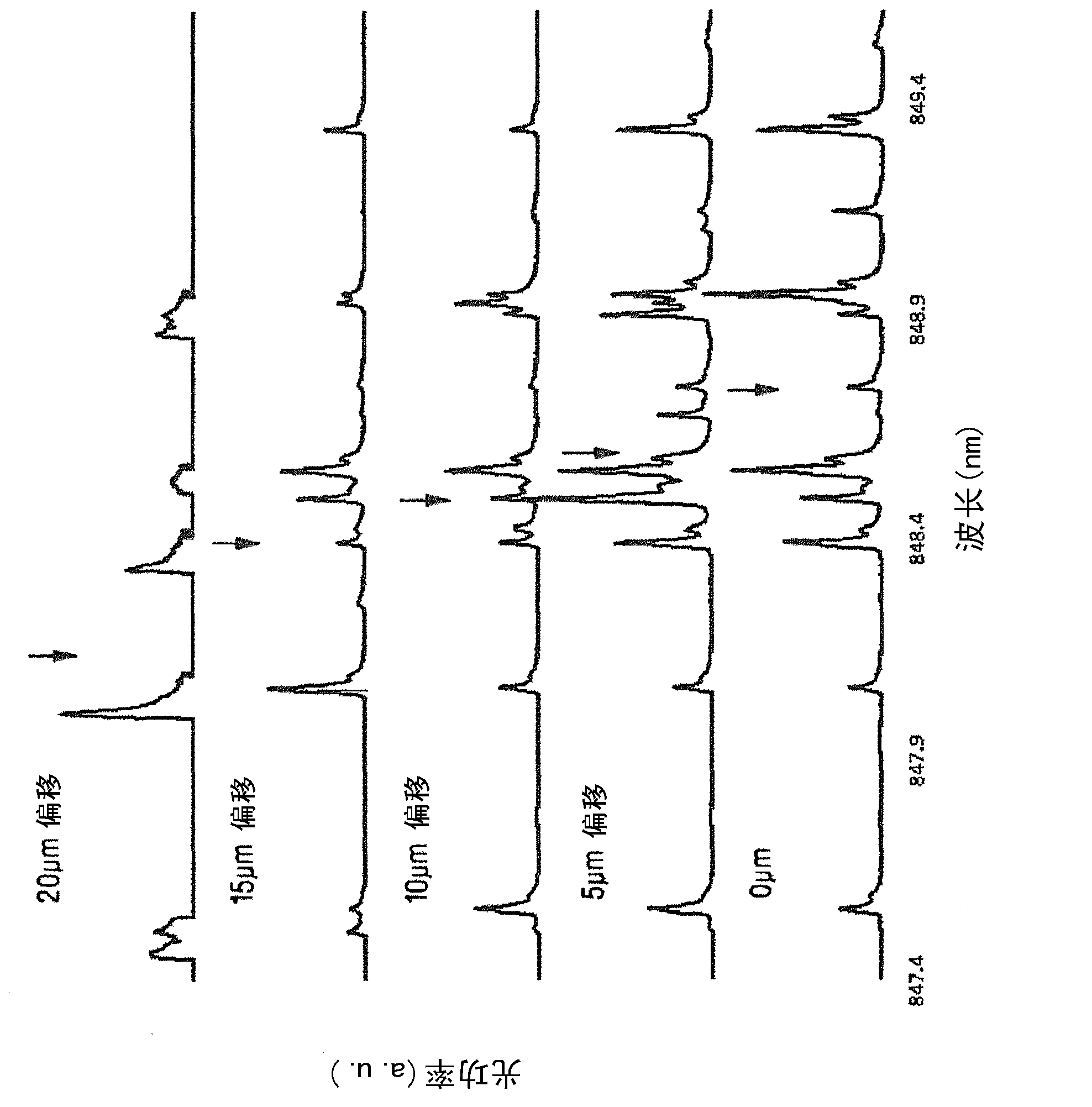
[0053] The present invention makes use of the discovery that due to the radially dependent wavelength emission pattern of the VCSEL and the way the light is coupled into the fiber, the fiber-coupled modes have a spectral composition that depends on the fiber radius and lead to non-negligible wavelength dispersion or material dispersion effect. figure 1 The spectra of various modes propagating in the MMF for five radial offsets on the fiber core are shown. The center wavelength or central wavelength of each radial spectrum is indicated by a downward arrow. Such as figure 1 As shown in , for this particular optical transmitter, on average, the center wavelength of the fiber mode shifts to shorter wavelengths for larger radial offsets. In addition to modal dispersion, this radial wavelength dependence causes the fiber modes to experience wavelength or material dispersion relative to each other. As a result, the refractive index profile must be modified to compensate for this...


PUM


Abstract

A method for compensating for both material or chromatic dispersion and modal dispersion effects in a multimode fiber transmission system is provided. The method includes, but is not limited to measuring a fiber-coupled spatial spectral distribution of the multimode fiber laser transmitter connected with a reference multimode fiber optical cable and determining the amount of chromatic dispersion and modal dispersion present in the reference multimode fiber optic cable. The method also includes, but is not limited to, designing an improved multimode fiber optic cable which compensates for at least a portion of the chromatic dispersion and modal dispersion present in the reference multimode fiber optic cable resulting from the transmitter's fiber-coupled spatial spectral distribution.

Description

technical field [0001] The present invention relates to a new differential mode delay (DMD) specification provided for the manufacture and use of laser-optimized multimode fiber optic cables (MMF) that exploit the radial dependence of the fiber-coupled wavelength distribution to Compensates for modal and wavelength dispersion to improve channel performance. [0002] The present invention also relates to a multimode fiber optic subassembly having a specified fiber coupled spatial spectral distribution. Such multimode fiber optic subassemblies include Multimode Fiber Transmitter Optical Subassemblies (TOSA) for use with specially designed MMFs. Knowledge of the fiber-coupled spatial spectral distribution allows compensation of the inherent chromatic dispersion in multimode fiber optical communication systems through specially designed MMFs, thereby facilitating improved system performance. Background technique [0003] Most high-speed optical channel links in short-range dat...

Claims


Application Information

Patent Timeline
IPC IPC(8): G01M11/00H04B10/2525
CPCG01M11/335G01M11/338H04B10/07951H04B10/2581G01M11/00H04B10/07G01M11/30G02B6/02214
Inventor G·E·图杜瑞R·J·皮姆皮娜拉B·莱恩
Owner PANDUIT
Why Eureka
Try Eureka