Fault-secure parking brake for motor vehicles

A parking brake and service brake technology, applied in the direction of brakes, brake components, brake control systems, etc., can solve the problems of high cost and expensive, and achieve the effect of simplifying the program structure

Active Publication Date: 2013-06-19
CONTINENTAL AUTOMOTIVE TECH GMBH
View PDF7 Cites 41 Cited by
  • Summary
  • Abstract
  • Description
  • Claims
  • Application Information

AI Technical Summary

Problems solved by technology

Thus, it is ensured that the vehicle is held against a single mistake, but the parking brake is expensive and therefore expensive

Method used


Image

  • Fault-secure parking brake for motor vehicles
  • Fault-secure parking brake for motor vehicles
  • Fault-secure parking brake for motor vehicles

Examples


Embodiment Construction

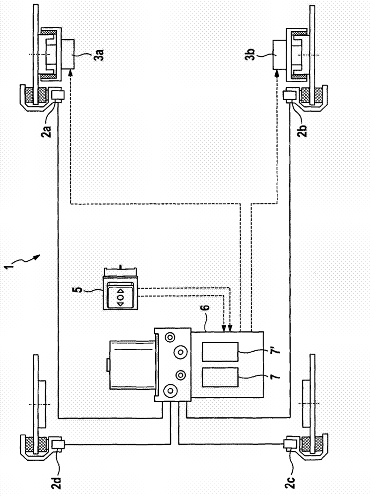
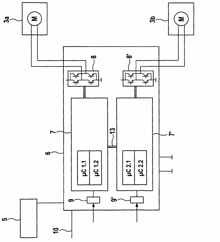
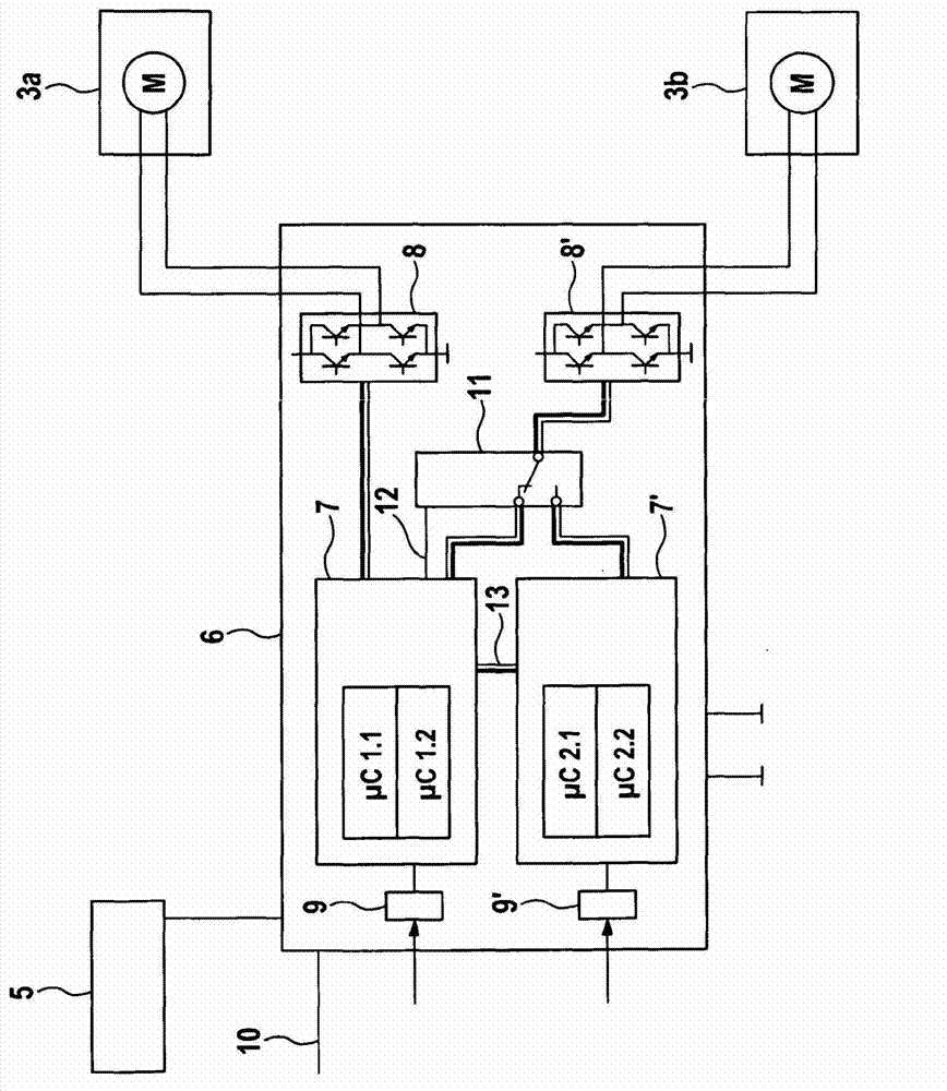
[0037] figure 1 An example of a braking system 1 is shown schematically, which is equipped with a service brake on all wheels and a parking brake on two wheels. In this case, the wheels of the rear axle have hydraulic friction brakes 2a, 2b and electric parking brake actuation means 3a, 3b, while the wheels of the front axle only have hydraulic friction brakes 2c, 2d. Both the service brake and the parking brake are connected to the electronic control unit 6, which has two separate computing units 7, 7' and which receives the driver's wish to actuate the electric parking brake via the parking brake actuation switch 5.

[0038] The service brakes can have hydraulic friction brakes or be fully or partially electromechanical. The control device 6 according to the invention implements a fault-tolerant parking brake with both a purely hydraulic service brake and a combined brake comprising, for example, a hydraulic brake on the front axle and an electromechanical friction brake on...


PUM


Abstract

The invention relates to an electronic control device for a brake system of a motor vehicle, comprising at least one interface for an operating element, in particular a parking brake operating switch, and at least two actuating circuits for electrical actuators, in particular electrical parking brake actuators. According to the invention, the electronic control device comprises two or more independent processors, which are directly connected to each other via a data bus. A motor vehicle equipped with a control device or brake system according to the invention requires no transmission lock in an automatic transmission.

Description

technical field [0001] The invention relates to an electronic control unit according to the preamble of claim 1 and to a braking system according to the preamble of claim 16 . Background technique [0002] Frequently, modern vehicles have an electric parking brake. The electric parking brake can be actuated by the driver via an actuating switch which is connected to an electronic control unit which actuates the actuation of a common or two separate parking brakes for both wheels mechanism. What is to be expected in terms of safety is that the electric parking brake works reliably even in the event of a single error. [0003] An electromechanical parking brake device for a motor vehicle is known from DE 19751431 A1, which comprises a brake operating device, an electronic control device for converting an input signal into a corresponding output signal, and two motor-operable parking brakes. The brake can be manipulated according to the output signal of the control device. ...

Claims


Application Information

Patent Timeline
Patent Type & Authority Applications(China)
IPC IPC(8): B60T7/04B60T7/10B60T8/17B60T13/66B60T13/74B60T17/22B60T8/1755B60T8/24B60T13/58
CPCB60T7/042B60T7/045B60T7/107B60T13/588B60T13/741B60T13/745B60T13/746B60T13/748B60T17/221B60T2270/413B60T7/10B60T8/17B60T8/1755B60T13/66B60T13/74B60T17/22B60T7/12
Inventor A·海泽K·沙德
Owner CONTINENTAL AUTOMOTIVE TECH GMBH
Why Eureka
Try Eureka