
A refrigerator drawer push-pull structure
A technology for drawers and refrigerators, which is applied to lighting and heating equipment, supports, household appliances, etc. It can solve problems such as easy shaking, small load-bearing capacity, and easy deformation of the drawer 8, and achieve the effect of avoiding cracking and enhancing load-bearing capacity
- Summary
- Abstract
- Description
- Claims
- Application Information
AI Technical Summary
Problems solved by technology
Method used
Image

Examples
Embodiment Construction
[0036] The present invention will be further described below in conjunction with specific embodiments.
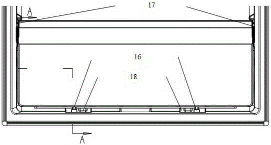
[0037] Such as Figure 3a , 3b As shown, the present invention discloses a drawer sliding structure of a refrigerator, comprising a box 20 and a drawer assembly mounted on the box 20 and capable of movably pushing and pulling, wherein the drawer assembly includes a drawer 11 and a first set on both sides of the drawer 11. The roller assembly and the second roller assembly arranged at the bottom of the drawer 11, the inner side of the box 20 is provided with a first guide rail 17 corresponding to the first roller assembly, and the inner side of the box 20 is provided with a second guide rail corresponding to the second roller assembly 18. The second guide rail 18 at the bottom of the box 20 is also provided with bottom rollers 16 for supporting the drawer 11 and rolling with the drawer 11. Specifically, the number of the bottom roller 16 is two.
[0038] Such as Figure 4 to 8 ...
PUM
 Abstract
Description
Claims
Application Information