Hydraulic pilot valve arrangement and hydraulic valve arrangement having the same

A technology for auxiliary valves and valve devices, applied in the field of hydraulic valve devices, can solve the problems that the switching speed cannot be increased arbitrarily, the high wear risk of the switching valve, and the valve is expensive

Inactive Publication Date: 2013-09-25
ROBERT BOSCH GMBH
View PDF3 Cites 3 Cited by
  • Summary
  • Abstract
  • Description
  • Claims
  • Application Information

AI Technical Summary

Problems solved by technology

[0006] The disadvantage of this solution is that the bandwidth required for the pressure medium volume flow still requires several switching valves of different nominal sizes
Although very rapidly switching valves with larger nominal widths can alternatively be used, such valves are more expensive
However, the switching speed cannot be increased arbitrarily, and in addition there is a higher risk of wear on the switching valve due to the rapid switching

Method used


Image

  • Hydraulic pilot valve arrangement and hydraulic valve arrangement having the same
  • Hydraulic pilot valve arrangement and hydraulic valve arrangement having the same
  • Hydraulic pilot valve arrangement and hydraulic valve arrangement having the same

Examples


Embodiment Construction

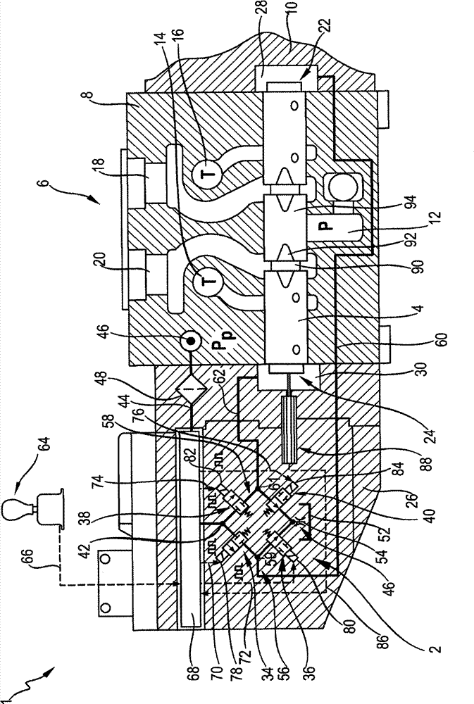
[0036] figure 1 Shown is a valve device 1 with an auxiliary valve device 2 which is flanged to a valve block 8 of a valve part 6 for actuating the valve body 4 or the valve part 6 configured as a 4 / 3 proportional directional valve. valve piston. Opposite the auxiliary valve arrangement 2 , an end disk 10 is flange-mounted on the valve block 8 . The valve part 6 has a high-pressure chamber 12 which can be connected to a high-pressure connection (not shown). Furthermore, the valve member 6 has low-pressure channels 14 and 16 which can be connected to a tank connection (not shown). In valve group 8 the figure 1 Two load connections 18 , 20 are arranged on the upper side in the middle, via which the valve element 6 can be connected to one or more loads.

[0037] according to figure 1 , the valve body 4 is in the central blocking position, so that the high-pressure chamber 12 is isolated from the load connections 18 , 20 and the low-pressure channels 14 , 16 . In the region o...


PUM


Abstract

The invention relates to a hydraulic pilot valve arrangement and a hydraulic valve arrangement having the same. The hydraulic pilot valve arrangement for pilot-controlling a valve includes at least one pilot valve configured to be activated electromagnetically in a pulse-width-modulated fashion. The pilot valve is configured to be activated ballistically or inversely ballistically. The hydraulic valve arrangement including the hydraulic pilot valve arrangement also has a valve configured to be pilot-controlled by the pilot valve arrangement.

Description

technical field [0001] The invention relates to a hydraulic auxiliary valve arrangement according to the preamble of claim 1 and to a hydraulic valve arrangement according to the preamble of claim 10 with the hydraulic auxiliary valve arrangement. Background technique [0002] According to the background art, the pressure medium volume flow can be actuated in a conventional manner via a continuously adjustable proportional directional valve with n connections and m switching positions. However, such a conventional similar pressure medium volume control device would significantly complicate the device and control technology. [0003] The application of digital hydraulic scheme makes it possible to simplify the device and control technology. Here, the individual control edges of conventional proportional directional valves are distributed by at least one valve element with at least one basic position and switching position In order to obtain as precise a control of the pres...

Claims


Application Information

Patent Timeline
Patent Type & Authority Applications(China)
IPC IPC(8): F15B13/02
CPCF15B11/006F15B13/043F15B21/08F15B2211/30575F15B2211/328F15B2211/355F15B2211/6336F15B2211/6346F15B2211/6355F15B2211/6656F15B2211/67Y10T137/86582Y10T137/87193
Inventor S·施密特
Owner ROBERT BOSCH GMBH
Why Eureka
Try Eureka