A light projection device and a camera including the light projection device

A light device and light source technology, applied in the camera field, can solve the problems affecting the luminous flux and uniformity of the outgoing light, wasting light, etc., and achieve the effect of good camera quality

Inactive Publication Date: 2016-01-27
BRIGHTEK (SHENZHEN) OPTOELECTRONIC CO LTD +1
View PDF5 Cites 0 Cited by
  • Summary
  • Abstract
  • Description
  • Claims
  • Application Information

AI Technical Summary

Problems solved by technology

However, the light source 101 usually generates a large amount of heat, and a heat sink 103 must be installed on its back, and a heat conducting member 104 may also be provided to dissipate the heat. figure 1 , 2 The heat-conducting element 104 has the function of conducting heat and supporting the light source 101 at the same time. Both the heat-dissipating element 103 and the heat-conducting element 104 are located at the front end of the reflector 102, which will inevitably block the light from being emitted, and will waste part of the light, affecting the luminous flux and uniformity of the outgoing light.

Method used


Image

  • A light projection device and a camera including the light projection device
  • A light projection device and a camera including the light projection device
  • A light projection device and a camera including the light projection device

Examples


Embodiment Construction

[0017] In order to make the object, technical solution and advantages of the present invention clearer, the present invention will be further described in detail below in conjunction with the accompanying drawings and embodiments. It should be understood that the specific embodiments described here are only used to explain the present invention, not to limit the present invention.

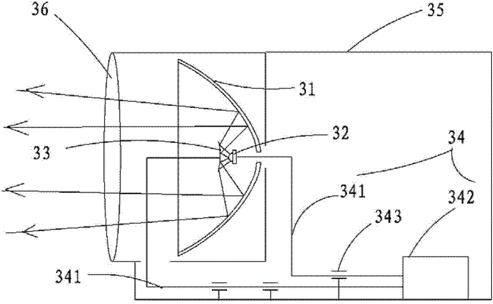
[0018] image 3 A schematic structural diagram of a light projection device provided by an embodiment of the present invention is shown, and for convenience of description, only parts related to this embodiment are shown.

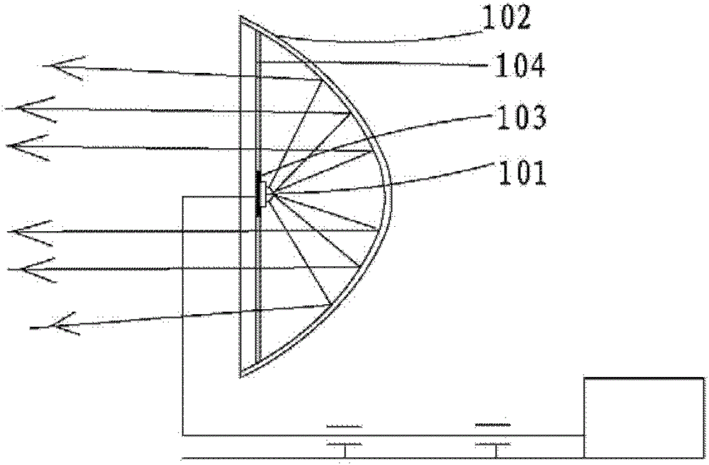
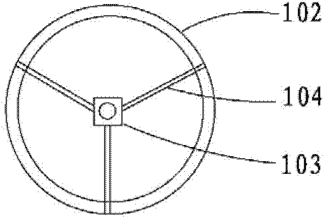
[0019] The light projecting device includes a main reflector 31 and a visible light source 32 arranged inside the main reflector 31. A sub-reflector 33 is arranged in the outgoing light direction of the visible light source 32. The central axis of the sub-reflector 33 and the main reflector 31 The openings of the main reflector 31 and the sub-reflector 33 are opposite to each o...


PUM


Abstract

The present invention is applicable to the technical field of photography, and provides a light projection device and a video camera including the light projection device. There is a secondary reflector, the secondary reflector is arranged coaxially with the main reflector and the opening is opposite, and the light projecting device also includes a driving component that can drive the visible light source and / or the secondary reflector to move along the central axis. The position of the visible light source and / or the sub-reflector in the present invention can be adjusted, so that the light exit angle can be changed at any time to match the viewing angle of the camera, so as to avoid the problems of poor imaging effect and low light utilization rate. At the same time, due to the installation of the sub-reflector, the visible light source does not need to be installed at the front end of the main reflector, and the visible light source, heat dissipation components and heat conduction components will not block the light emission, which solves the problem that the light source and heat dissipation components in the traditional light projection device affect the outgoing luminous flux. Thus ensuring good camera quality.

Description

technical field [0001] The invention belongs to the field of imaging, and in particular relates to a light projection device and a video camera including the light projection device. Background technique [0002] A video camera is a device that collects dynamic or static image information of a subject. It can be used in various fields such as security, transportation, art, and daily shooting. The camera is usually equipped with a lighting system to emit light to the subject. The lighting After the light is reflected by the subject, it is captured by the imaging device of the camera, the light information is converted into an electrical signal, and the image of the subject is formed after corresponding data processing. Most of the light sources used by existing cameras have fixed light emission angles, and after the cameras leave the factory, their illumination angles are also fixed accordingly. However, when the angle of view of the camera is adjusted to be small in order t...

Claims


Application Information

Patent Timeline
Patent Type & Authority Patents(China)
IPC IPC(8): G03B15/05H04N5/225F21V7/10F21Y101/02G03B15/06
Inventor 黄建中李锦泉
Owner BRIGHTEK (SHENZHEN) OPTOELECTRONIC CO LTD
Why Eureka
Try Eureka