Gas wiping device

A gas and gas flow path technology, which is applied in metal material coating process, hot-dip plating process, coating, etc., can solve problems such as disturbing gas flow, achieve the effect of eliminating over-coating or splashing, and simple structure improvement

Active Publication Date: 2014-01-08
NIPPON STEEL & SUMIKIN ENG CO LTD +1
View PDF5 Cites 3 Cited by
  • Summary
  • Abstract
  • Description
  • Claims
  • Application Information

AI Technical Summary

Problems solved by technology

The gas (X3 direction) introduced from the rear of the gas wiping device W flows forward through its cavity and is ejected from the gas outlet E (X4 direction), but the gas flowing through the cavity and reaching the blocking parts H, H The flow is sharply constricted toward the center (X5 direction), and the above-mentioned vortex is generated by the sharp constriction, and the vortex disturbs the gas flow, causing intermittent overcoating or splashing at the end of the strip in the width direction.

Method used


Image

  • Gas wiping device
  • Gas wiping device
  • Gas wiping device

Examples


Embodiment approach 1

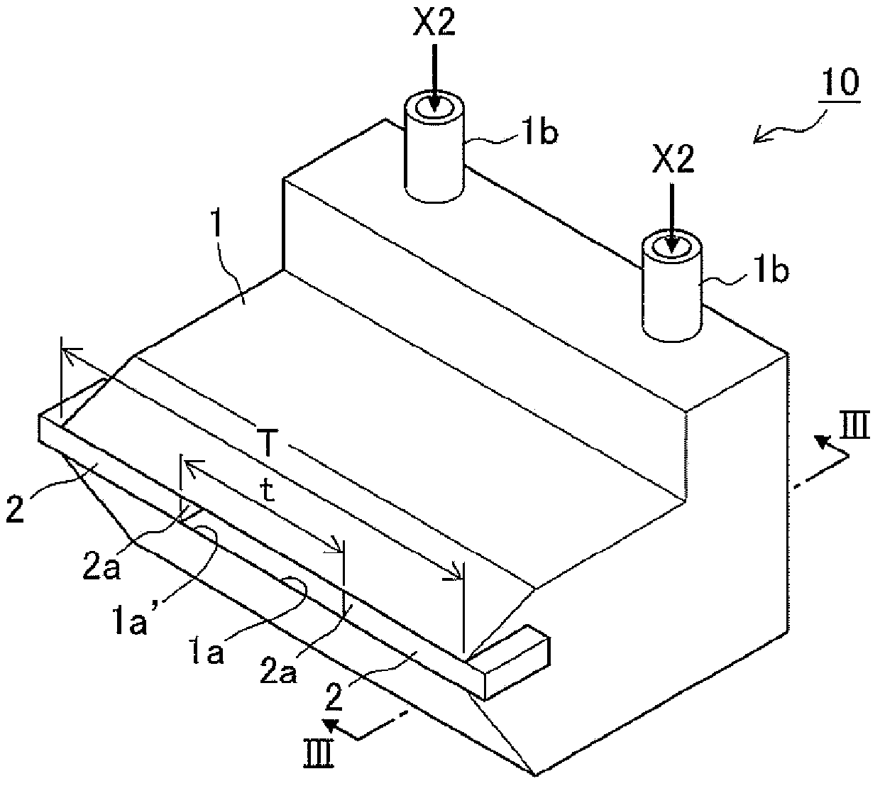
[0053] figure 2 It is a three-dimensional representation of the composition figure 1 A diagram of an embodiment of the gas wiping device of the electroplating device, image 3 yes figure 2 III-III direction view, Figure 4 yes image 3 IV-IV direction view.

[0054] Figure 2 ~ Figure 4 The gas wiping device 10 shown in is roughly composed of a gas wiping nozzle 1 having a cavity, and a gas (not shown) that is provided behind and supplies gas to a gas inflow pipe 1b that supplies gas to the cavity of the gas wiping nozzle 1. Supply device (gas supply source) configuration.

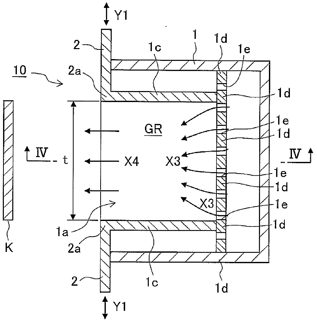
[0055] Furthermore, the gas wiping nozzle 1 has a slit 1a' (its overall width is T) extending along the width direction of the steel strip K and blowing gas from its cavity. And the left and right closing members 2, 2 are slidable (Y1 direction) along the gap 1a', and the gas outlet 1a is formed in the gap region between the separated left and right closing members 2, 2.

[0056] A gas inflow pi...

Embodiment approach 2)

[0064] Figure 5 is a cross-sectional view of another embodiment of the gas wiping device, based on the image 3 The graph corresponding to the representation of the form, Figure 6 yes Figure 5 The VI-VI direction view.

[0065] In the gas wiping device 10A shown in the figure, in the gas flow path GR, a hanging piece 3a that does not reach the lower surface is fixed on the upper surface of the cavity, and a hanging piece 3a that does not reach the upper surface is fixed on the lower surface of the cavity at a position away from the hanging piece 3a. The gas introduced into the gas channel GR from the gas inlet 1e is rectified during the process (X3') of flowing through these hanging pieces 3a and the vertical pieces 3b.

[0066] The other ends of the left and right rectifying pieces 1c, 1c are located in front of the standing piece 3b or the hanging piece 3a, and slide in front of the standing piece 3b and the hanging piece 3a according to the width change of the gas out...

Embodiment approach 1)

[0070] Next, refer to Figure 7 , Embodiment 1 of the sliding mechanism of the left and right blocking members will be described by taking the gas wiping device 10 as an example.

[0071]In the sliding mechanism shown in the figure, the left and right blocking members 2, 2 are slidable to the left and right by the inherent left sliding mechanism 5A and right sliding mechanism 5B, respectively, and the left sliding mechanism 5A and the right sliding mechanism 5B are mounted on the common base 6. , the common base 6 is connected with the base sliding mechanism 7 so as to slide freely.

[0072] The left blocking member 2 and the electric slider constituting the left sliding mechanism 5A are connected by two wires W1, W1 via a pulley 9 to form a roughly ring shape, whereby when the left sliding mechanism 5A slides left and right (Z1 direction), the left blocking member 2 also slides freely to the left and right synchronously (Z1' direction). Similarly, the right blocking part 2 ...


PUM

PropertyMeasurementUnit
thicknessaaaaaaaaaa

Abstract

This invention relates to a gas wiping device provided with a gas wiping nozzle which sprays a gas onto the surface of the steel strip to adjust the amount of a molten metal for plating which adheres to said surface, said gas wiping device having excellent overcoat and splash suppression at the ends of the steel strip in the width direction. This gas wiping device (10) is provided in a gas wiping nozzle (1) with a slit (1a') which extends in the width direction of a steel strip (K) and sprays a gas from a hollow space, and with gas inlets (1e) for introducing the gas into the hollow space; in the slit (1a') are provided left and right blocking members (2, 2) which freely slide and block the left and right regions of said slit, and a gas outlet port (1a) is formed between the left and right blocking members (2, 2); in the hollow space are provided left and right rectifier pieces (1c, 1c) which extend from the outlet port-side ends (2a, 2a) of the left and right blocking members (2, 2) to a partition wall (1d), forming a gas flow path (GR) between the left and right rectifier pieces (1c, 1c), wherein the width of the gas outlet port (1a) and the width of the gas flow path (GR) are the same.

Description

technical field [0001] The present invention relates to a gas wiping device which sprays gas on the surface of a steel strip which is continuously conveyed and immersed in an electroplating bath to adjust the amount of molten metal for electroplating adhering to the surface. Background technique [0002] When the steel strip is continuously immersed in a molten metal electroplating bath for molten metal electroplating, generally so-called gas wiping is performed to adjust the adhesion amount of molten metal by spraying gas to the unsolidified electroplating surface of the dipped steel strip, for example, in continuous Gas wiping devices equipped with gas wiping nozzles are arranged on both sides of the conveyed steel strip, and gas wiping is performed by blowing gas to both sides of the steel strip. [0003] The gas wiping nozzle has an elongated shape corresponding to the length in the width direction of the steel strip that is immersed in the molten metal in the plating ta...

Claims


Application Information

Patent Timeline
Patent Type & Authority Applications(China)
IPC IPC(8): C23C2/20C23C2/40
CPCC23C2/20C23C2/40C23C2/18C23C2/16
Inventor 若林久干胜部诚西川广
Owner NIPPON STEEL & SUMIKIN ENG CO LTD
Why Eureka
Try Eureka