
Movable emergency lamp
A mobile, lighting technology, applied in the direction of electric light circuit layout, portable lighting devices, lighting auxiliary devices, etc., can solve the problems of power waste, inability, inconvenient to move, etc., and achieve the effect of saving power
- Summary
- Abstract
- Description
- Claims
- Application Information
AI Technical Summary
Problems solved by technology
Method used
Image

Examples
Embodiment Construction
[0021] The following will clearly and completely describe the technical solutions in the embodiments of the present invention with reference to the drawings in the embodiments of the present invention.
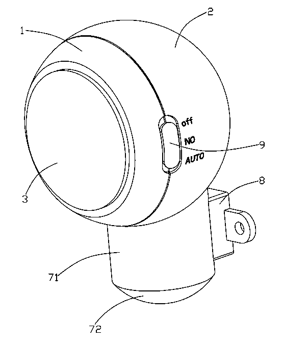
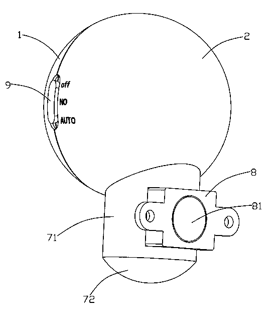
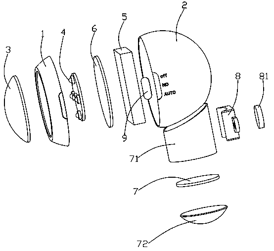
[0022] Such as Figure 1~Figure 3 As shown, a mobile emergency lamp provided by the embodiment of the present invention includes a front shell 1 and a rear shell 2 that cooperate with each other. The front shell 1 cooperates with a transparent cover 3 to allow light to pass through the transparent cover 3. The front shell 1 and the rear shell 2 are equipped with a light source 4, a power source 5 electrically connected to the light source 4, and a control circuit board 6. The control circuit board 6 is provided with a light sensor switch circuit (not shown), and the light source 4 passes the light The induction switch circuit is electrically connected to the power supply 5 , and an optical sensor 7 electrically connected to the control circuit board 6 is provided outside the r...
PUM
 Abstract
Description
Claims
Application Information