Trigger board connector for thyristor valve

A technology of thyristor valve and trigger board, which is applied in the direction of connection, two-part connection device, and parts of the connection device, etc., can solve the problems of small contact area between pins and jacks, poor electrical conductivity, and long connector terminals. , to achieve the effect of light weight, low contact resistance, long plug life

Inactive Publication Date: 2014-02-26
STATE GRID CORP OF CHINA +2
View PDF7 Cites 2 Cited by
  • Summary
  • Abstract
  • Description
  • Claims
  • Application Information

AI Technical Summary

Problems solved by technology

[0005] At present, the trigger board connectors on the market use split jacks, the contact area between the pins and the jacks is small, the electrical conductivity is poor, and it is easy to cause poor contact; the insertion force is unstable during installation and debugging, and the pins are easily damaged. , It is relatively difficult to replace; and the connector terminal is long, bulky, and takes up space

Method used


Image

  • Trigger board connector for thyristor valve
  • Trigger board connector for thyristor valve
  • Trigger board connector for thyristor valve

Examples


Embodiment Construction

[0036] The specific implementation manners of the present invention will be further described in detail below in conjunction with the accompanying drawings.

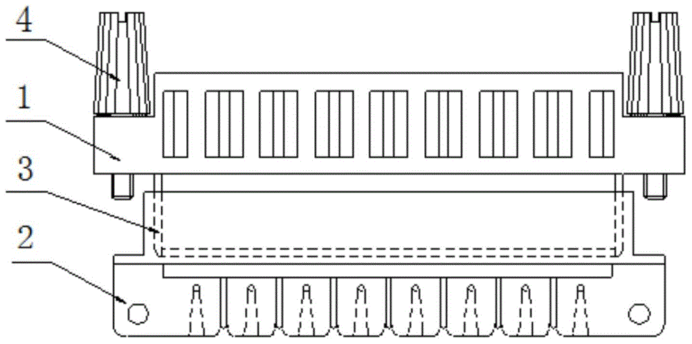
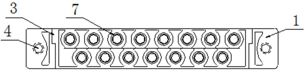
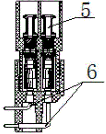
[0037] In this embodiment, the trigger board connector for a thyristor valve is taken as an example, such as Figure 1 to Figure 10 As shown, the thyristor valve trigger plate connector provided by the embodiment of the present invention includes: plug 1, socket 2, limit groove 3, long knurled captive screw 4, socket 5, pin 6, positioning hole 7, Fixing hole 8, trigger plate 9, wire 10, wire spring wire 11, test hole 12, test pin 13.

[0038] Both the plug 1 and the socket 2 are provided with chamfers at the entrance of the insulator, and are provided with a corresponding convex and concave limit groove 3. The limit groove 3 is a rectangle with a gap, which has a preliminary guiding effect on the connector and the plug 1 is inserted into the socket. 2. The anti-error function enables the plug 1 to enter the socket 2 smo...


PUM


Abstract

The invention provides a trigger board connector for a thyristor valve. The connector comprises a plug and a socket which are correspondingly arranged in a separated mode, wherein the plug and the socket are provided with convex and concave matching stop slots, and the stop slot of the plug is internally and vertically provided with positioning holes side by side. The connector is characterized in that the positioning holes are provided with jacks, and the socket is provided with needles in matching with the jacks. Compared with the prior art, the trigger board connector for the thyristor valve has advantages of low and stable contact resistance, small plugging force, low contact wearing, long plugging service life and maintained high reliability of electrical contact under a strong vibration impact environment.

Description

technical field [0001] The invention relates to a trigger board connector, in particular to a trigger board connector for a thyristor valve. Background technique [0002] The development of high-voltage direct current transmission has a history of more than one hundred years, and it played a role in the early stage of the development of power transmission technology. However, at the beginning of the 20th century, due to the complex operation of DC motors in series, and the difficulty in commutation of high-voltage and large-capacity DC motors, etc. problems, making DC transmission technically and economically uncompetitive with AC transmission, so progress has been slow. After the 1970s, with the rapid development of power electronics and microelectronics technology, the emergence of high-voltage and high-power thyristors, the application of thyristor converter valves and computer control in DC transmission projects, effectively improved the operating performance and perform...

Claims


Application Information

Patent Timeline
Patent Type & Authority Applications(China)
IPC IPC(8): H01R13/631H01R13/64H01R13/187H01R13/24H01R24/00
Inventor 常忠赵刚王承民袁洪亮张雷牟连树任西周郎平张伟华
Owner STATE GRID CORP OF CHINA
Why Eureka
Try Eureka