A Vortex Generator Structure for Suppressing Boundary Layer Separation Under Shock Wave

A vortex generator and boundary layer technology, applied in the direction of fluid flow, mechanical equipment, etc., can solve the problems of anti-separation, restriction, and mutual weakening of unfavorable boundary layers, so as to improve the anti-separation ability, have small mutual weakening effect, and reduce separation The effect of zone size

Active Publication Date: 2015-10-07
INST OF ENGINEERING THERMOPHYSICS - CHINESE ACAD OF SCI
View PDF4 Cites 0 Cited by
  • Summary
  • Abstract
  • Description
  • Claims
  • Application Information

AI Technical Summary

Problems solved by technology

However, since the vortices induced by the existing vortex generator structure have a mutual weakening effect and are rapidly lifted away from the wall boundary layer, its role in controlling the boundary layer is limited, which is not conducive to further improving the ability of the boundary layer to resist separation

Method used


Image

  • A Vortex Generator Structure for Suppressing Boundary Layer Separation Under Shock Wave
  • A Vortex Generator Structure for Suppressing Boundary Layer Separation Under Shock Wave
  • A Vortex Generator Structure for Suppressing Boundary Layer Separation Under Shock Wave

Examples


Embodiment approach

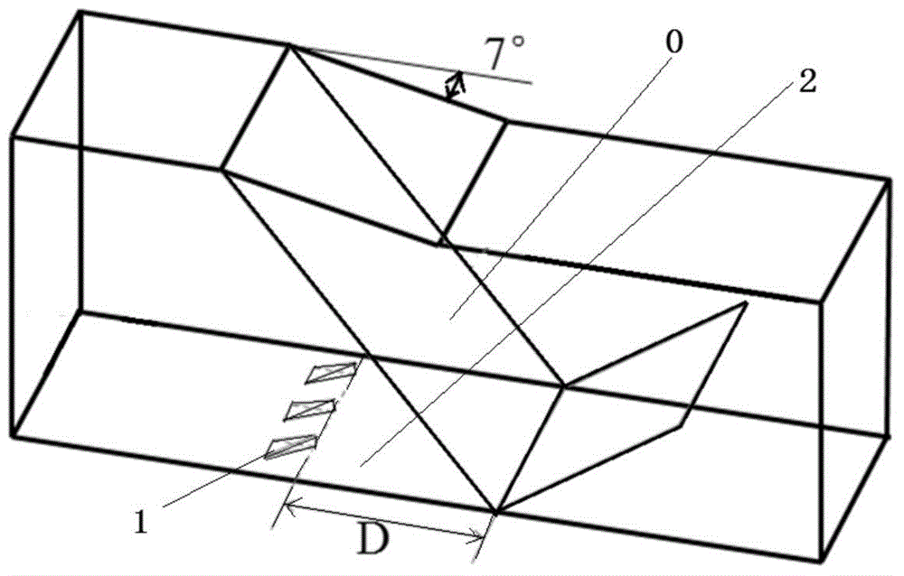
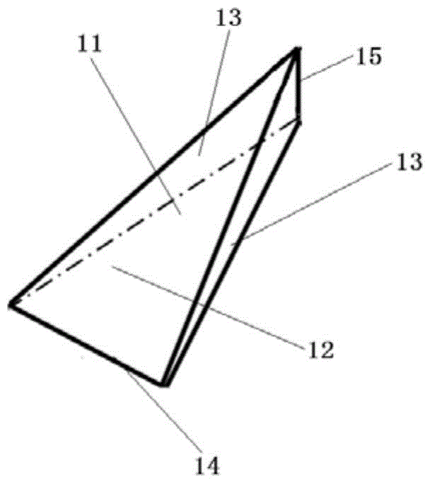
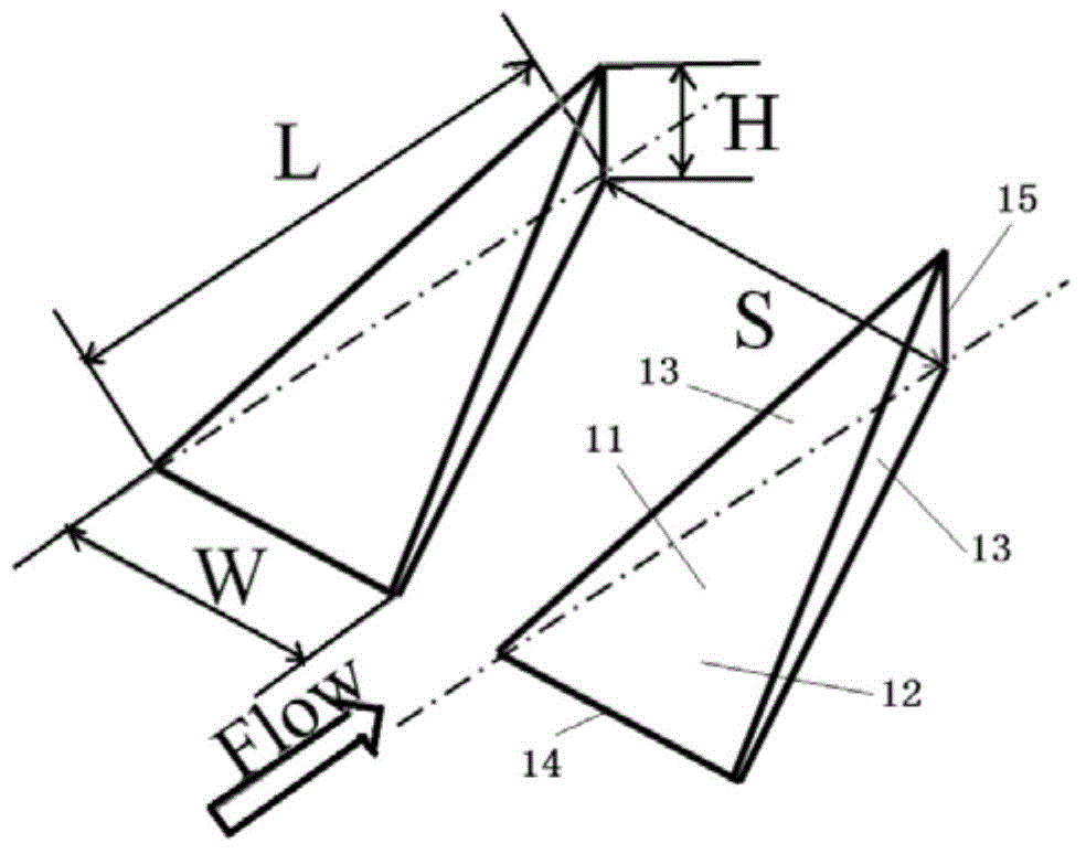
[0028] As an implementation, for example, the height H of the trailing edge of the vortex generator can be 70% of the boundary layer thickness B when there is no vortex generator control at the position; the length L along the flow direction is 7 times the height H of the trailing edge of the vortex generator ; The spanwise width W in the vertical flow direction is 3 times the height H of the trailing edge; the spacing S between adjacent structures in the arrangement of vortex generators is 7.5 times the height H of the trailing edge.

[0029] Numerical calculation results show that the incompressible shape factor of the boundary layer downstream of the shock boundary layer interaction zone decreases from 1.47 without control to 1.39 with vortex generator control. The incompressible shape factor of the boundary layer is the ratio of the displacement thickness to the momentum thickness of the boundary layer. The value of the shape factor is inversely proportional to the ability ...


PUM


Abstract

The invention relates to a vortex generator structure for suppressing boundary layer separation under the action of shock waves. One or more vortex generator structures arranged in parallel are arranged, so that a flow control device is obtained. The flow control device aims at improving separation-resistant capacity of boundary layers in ultrasonic gas flowing under the action of the shock waves. A vortex generator is of a tetrahedral structure basically and is located in an interference region upstream boundary layer where shock wave boundary layers interact, the distance between a vortex generator trailing edge and an interference region initial point is 15-30 times of a boundary layer thickness when no control exists in the position where the vortex generator is located, the height of the vortex generator trailing edge is 0.3-0.8 time of a boundary layer thickness when no control exists in the position where the vortex generator is located, the length is directly proportional to the trailing edge height of the vortex generator, the specific value of the length to the trailing edge height is 5 to 10, the width is directly proportional to the trailing edge height of the vortex generator, the specific value of the width to the trailing edge height is 2 to 4, the distance between vortex generators is directly proportional to the trailing edge height of the vortex generator, and the specific value of the distance to the railing edge height is 6 to 10. The vortex generator structure is suitable for supersonic flow fields where the shock waves induce separation of boundary layers.

Description

technical field [0001] The invention relates to the field of supersonic flow control, and relates to a control device for improving the ability of a boundary layer to resist separation under the action of a shock wave, in particular to a vortex generator structure for suppressing the separation of the boundary layer under the action of a shock wave. Background technique [0002] Shock boundary layer interference is an aerodynamic phenomenon in supersonic gas flow, which is commonly found in supersonic inlets and supersonic compressors. The existence of the shock boundary layer interference phenomenon can easily induce the separation of the boundary layer, deteriorating the flow field, resulting in the limitation of the airflow pressurization capacity, and increasing the flow loss, which is not conducive to improving the efficiency of the compressor and the inlet. The vortex generator is a device used to improve the flow field separation induced by the shock boundary layer in...

Claims


Application Information

Patent Timeline
Patent Type & Authority Patents(China)
IPC IPC(8): F15D1/06
Inventor 赵庆军孙小磊项效镕徐建中
Owner INST OF ENGINEERING THERMOPHYSICS - CHINESE ACAD OF SCI
Why Eureka
Try Eureka