Apparatus for modelling ocular structures

A technology of optical components and beams, used in the field of eye modeling, to solve problems such as failure

Active Publication Date: 2014-04-16
ALCON INC
View PDF8 Cites 4 Cited by
  • Summary
  • Abstract
  • Description
  • Claims
  • Application Information

AI Technical Summary

Problems solved by technology

Failure to resolve the refractive index leads to errors...

Method used


Image

  • Apparatus for modelling ocular structures
  • Apparatus for modelling ocular structures
  • Apparatus for modelling ocular structures

Examples


Embodiment Construction

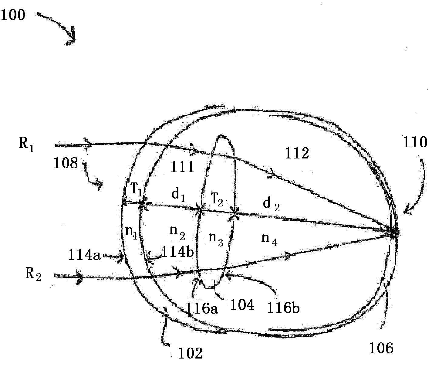
[0076] Apparatus and methods for modeling one or more eye structures are described. Modeling will indicate the shape and / or location of eye structures, which can be determined using optical methods used to determine one or more ocular structures of interest, as well as structures in front of the ocular structures of interest. The one or more parameters include shape, thickness, distance and refractive index.

[0077] Measurements of either the shape, thickness, and / or refractive index of any ocular structure of interest will use the orientation of the light according to some measurement technique experienced by the light as it passes through the ocular structure in front of any ocular structure of interest Change the range on. Thus, depending on the technique, measurements of shape, thickness, and / or one aspect of the refractive index of an ocular structure are corrected as a basis for measuring the values ​​of other parameters of this structure, as well as any parameter of t...


PUM


Abstract

An imaging system for an optical element, the imaging system comprising means for illuminating a targeted optical element with at least one incident light beam and means for directing at least two light beams returning from at least one surface of the illuminated optical element onto a detector; the detector adapted to measure relative light characteristics of the at least two returning light beams and to calculate at least one parameter of the optical element using the measured characteristics of the at least two returning light beams.

Description

technical field [0001] The present invention relates to eye modeling. Background technique [0002] Eye surgery typically modifies one or more structures of the eye, such as the cornea, lens, or retina. Some surgeries involve removing or replacing one or more eye structures, or adding a graft. For example, lens replacement surgery involves removing a patient's existing lens and replacing it with a new lens. Some procedures, such as laser vision correction surgery, do not remove or replace a patient's existing structures, or add implants in the eye, but reshape existing structures. Regardless of the modification made (eg, removal, replacement, insertion, or remodeling), the optical properties of the eye are altered by the adjustments made to the structure of the eye. It is therefore necessary to determine the ocular parameters of the eye in order to accurately model any eye structure. These parameters include shape, thickness, and refractive index of ocular structures suc...

Claims


Application Information

Patent Timeline
IPC IPC(8): A61B3/10A61B3/107A61B3/14A61B3/135A61F9/008
CPCA61B3/107A61B3/1005A61B3/145A61F2009/00878A61B3/135A61B3/14
Inventor E·恩格A·甘查拉夫P·柯林斯
Owner ALCON INC
Why Eureka
Try Eureka