Front subframe and producing method thereof

A technology of front sub-frame and front side components, which is applied to vehicle parts, substructure, transportation and packaging, etc. It can solve the problems of bracket deformation welding stress, effort discount, increase of production cost, etc., and achieve the effect of improving the force strength

Active Publication Date: 2014-04-23
ANHUI JIANGHUAI AUTOMOBILE GRP CORP LTD
View PDF5 Cites 4 Cited by
  • Summary
  • Abstract
  • Description
  • Claims
  • Application Information

AI Technical Summary

Problems solved by technology

However, the problem with implementing this method is that the welding of the upper plate 101 and the lower plate 102 is a large-scale welding along the edges of the two plates, which is different from the welding method and welding robot used when welding the front mounting bracket 103 After completing the welding of the upper plate 101 and the lower plate 102, returning to weld the front side wall 1031 of the front mounting bracket 103 will obviously affect the production beat, and adding a welding position and welding robot on the production line will bring production cost increase
Therefore, for the sake of cost saving, after the tack welding of the front mounting bracket 103 on the lower plate 102 is completed, the welding of the front side wall 1031 will not be carried out. Depend on image 3 The upper plate 101 or the front side wall 1031 in the middle are separately stressed, for example, the force from front to rear is borne by the upper plate 101 alone, and the force from back to front is borne by the front side wall 1031 alone, which makes the technician greatly discounted efforts
Secondly, even if the cost input is increased in order to solve the welding problem, the problem of inaccurate positioning of the separate front mounting bracket 103 cannot be solved, and if there is a large amount of welding in the front mounting bracket 103, it will cause deformation of the bracket and concentration of welding stress, which will give Subsequent vehicle assembly creates trouble

Method used


Image

  • Front subframe and producing method thereof
  • Front subframe and producing method thereof
  • Front subframe and producing method thereof

Examples


Embodiment Construction

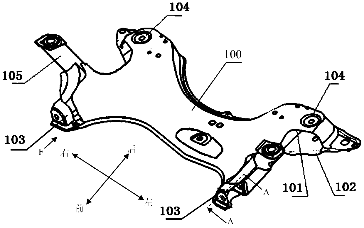
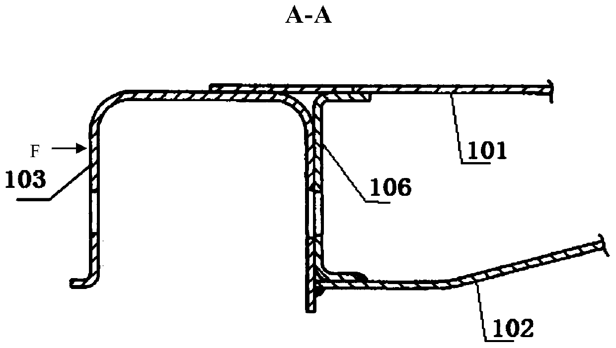
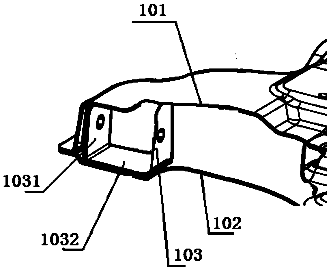
[0030] refer to Figure 5 , it can be seen that the front side member 105 and the front mounting bracket 103 are integrally stamped and formed. Front mounting bracket 103 has front side wall 1031, bottom wall 1032 and rear side wall 1033, and for front side member 105, it has a common wall portion 1033 with front mounting bracket 103, and this wall 1033 and front side member 105 The other side wall 1053 of the front side member 105 and the bottom wall 1054 of the front side member 105 jointly form a groove structure. Moreover, the upper end 1051 of the front side member 105 is used to realize connection with the vehicle body, and the lower end 1052 has a flange structure for realizing welding with the lower plate 102 . On the wall patch 1033, a boss 1034 is stamped.

[0031] refer to Figure 6 , is an exploded view of the front subframe in the embodiment of the present invention, and shows the welding sequence of the front subframe in the embodiment of the present invention. ...


PUM


Abstract

The invention provides a front subframe comprising an upper plate and a lower plate which are connected to form a front subframe body, and a front component used for connecting the front subframe body to a vehicle. A lower swing arm front mounting support and a lower swing arm rear mounting portion are arranged between the upper plate and the lower plate on the left and right sides of the front subframe body. The front component and a front mounting support are punched and formed integrally. The front wall of the front mounting support is welded to the upper plate or the lower plate, and the bottom wall is connected to the lower plate in welded manner so that a front-rear double-layered reinforcing structure and an upper-lower double-layered reinforcing structure are formed. The invention further provides a method for producing the front subframe. The front subframe has the advantages of high strength, convenience of welding and high positioning accuracy.

Description

technical field [0001] The invention relates to the field of automobile frame. Background technique [0002] As an important load-bearing part of the car, the front subframe supports and connects multiple parts of the car, including key components such as the steering mechanism, powertrain, and stabilizer bar assembly. Its fatigue life and dimensional accuracy play a vital role in the safety and performance of the vehicle. [0003] There are two types of front sub-frames: castings and welded plates. The latter is more and more widely used because of its good fuel economy. However, it is inevitable that the car will suffer from frequent starting, braking, acceleration and deceleration, Forces in the front and rear directions, left and right directions, and up and down directions generated by bumps are transmitted to the front subframe through the lower swing arm of the suspension. For simplicity, only the front and rear direction force F is marked in the drawings. However, ...

Claims


Application Information

Patent Timeline
Patent Type & Authority Applications(China)
IPC IPC(8): B62D21/00
Inventor 胡春波李磊杨子平殷吕
Owner ANHUI JIANGHUAI AUTOMOBILE GRP CORP LTD
Why Eureka
Try Eureka